EasyManua.ls Logo

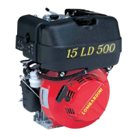
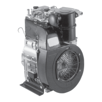
Lombardini 15 LD 315 User Manual

Lombardini 15 LD 315
74 pages
To Next Page IconTo Next Page
Page #1 background imageLoading...
Page #1 background image
1
15 LD 225
15 LD 315
15 LD 350
15 LD 400
15 LD 440
DATE
22.12.2003
COMPILER TECO/ATI
REG. CODE
1-5302-467
MODEL N°
50707
DATE OF ISSUE
06-95
REVISION 05
ENDORSED
6
th
Edition
WORK SHOP
MANUAL
15LD series engines, p.no. 1-5302-467

Table of Contents

Other manuals for Lombardini 15 LD 315

Questions and Answers:

Lombardini 15 LD 315 Specifications

General IconGeneral
BrandLombardini
Model15 LD 315
CategoryEngine
LanguageEnglish

Summary

General Service Notes

Genuine Parts Recommendation

Emphasizes using genuine Lombardini spare parts for optimal engine performance and longevity.

Metric System Convention

Manual adheres to the metric system for all measurements and specifications.

Warranty Certificate

Model Number and Identification

Engine Model Number Details

Details on engine displacement, type, and manufacturer.

Engine Identification Details

Information on RPM, customer code, approval code, and serial number.

Technical Data

CHARACTERISTICS: 15 LD 225, 15 LD 315, 15 LD 350

Technical specifications for 15 LD 225, 15 LD 315, and 15 LD 350 engines.

Technical Data

CHARACTERISTICS: 15 LD 400, 15 LD 440

Technical specifications for 15 LD 400 and 15 LD 440 engines.

Characteristics

POWER, TORQUE, FUEL CONSUMPTION CURVES (15 LD 225, 315, 350)

Graphs showing power, torque, and fuel consumption for 15 LD 225, 315, 350.

Characteristics

POWER, TORQUE, FUEL CONSUMPTION CURVES (15 LD 400, 440)

Graphs showing power, torque, and fuel consumption for 15 LD 400, 440.

Overall Dimensions

OVERALL DIMENSIONS: 15 LD 225

Overall dimensions and detailed drawings for the 15 LD 225 engine.

Overall Dimensions

OVERALL DIMENSIONS: 15 LD 400

Overall dimensions and detailed drawings for the 15 LD 400 engine.

OVERALL DIMENSIONS: 15 LD 440

Overall dimensions and detailed drawings for the 15 LD 440 engine.

Maintenance - Recommended Oil Type - Refilling

MAINTENANCE SCHEDULE AND INTERVALS

Scheduled maintenance operations and intervals for engine components.

FUELING GUIDELINES AND TANK CAPACITY

Guidelines for refueling, fuel types, and tank capacity for different engine models.

Maintenance - Recommended Oil Type - Refilling

RECOMMENDED OIL SPECIFICATIONS AND GRADES

Specifications and grades of recommended engine oils based on temperature.

Disassembly/Reassembly

GENERAL DISASSEMBLY/REASSEMBLY PROCEDURES

General procedures for disassembly, reassembly, specifications, and operating instructions.

DRY AIR CLEANER MAINTENANCE (15 LD 315, 350)

Instructions for cleaning and maintenance of the dry air cleaner for specific engine models.

Disassembly/Reassembly

DRY AIR CLEANER MAINTENANCE (15 LD 400, 440)

Procedure for opening, cleaning, and refitting the dry air cleaner for 15LD 400-440.

DRY AIR FILTER PREFILTER MAINTENANCE

Instructions for removing and cleaning the pre-filter for the dry air cleaner.

Disassembly/Reassembly

OIL-BATH AIR CLEANER (OPTIONAL) COMPONENTS

Components and maintenance of the optional oil-bath air cleaner.

MUFFLER REASSEMBLY PROCEDURE

Procedure for reassembling the muffler, including tightening torques.

Disassembly/Reassembly

ROCKER ARM COVER BREATHER SYSTEM

Explanation of crankcase vapor recirculation via the rocker arm cover.

VALVE/ROCKER ARM CLEARANCE SETTING (15 LD 225-315-350)

Procedure for setting valve/rocker arm clearance for specific engine models.

Disassembly/Reassembly

HYDRAULIC TAPPETS (15 LD 400-440) ASSEMBLY

Details on hydraulic tappets and their assembly for 15 LD 400-440 engines.

Disassembly/Reassembly

FUEL TANK REMOVAL AND REFILLING PROCEDURE

Procedure for removing, emptying, and refitting the fuel tank.

EXTERNAL FUEL FILTER COMPONENTS (15 LD 225-315-350-400-440)

Components and characteristics of the external fuel filter.

Disassembly/Reassembly

RE-COIL STARTING SYSTEM COMPONENTS AND OPERATION

Components and operation of the re-coil starting system.

SHROUD INSTALLATION AND NOISE REDUCTION

Description of the shroud's material and its noise absorption properties.

Disassembly/Reassembly

CYLINDER HEAD REMOVAL AND REASSEMBLY

Procedure for cylinder head removal, flattening, and bolt tightening.

INJECTOR PROJECTION SETTING PROCEDURE

Method for setting injector nozzle projection using copper gaskets.

Disassembly/Reassembly

VALVE DISASSEMBLY PROCEDURE

Components and procedure for disassembling engine valves.

VALVE OIL SEAL INSTALLATION INTO GUIDE

Method for fitting the oil seal into the valve guide using a specific tool.

Disassembly/Reassembly

VALVE CHARACTERISTICS AND MATERIALS

Material and dimensional characteristics of intake and exhaust valves.

VALVE GUIDES AND HOUSINGS DIMENSIONS

Dimensions for valve guides and housings for different engine models.

Disassembly/Reassembly

VALVE GUIDE TO STEM CLEARANCES

Table showing dimensions and clearances for valve guides and stems.

VALVE SEAT AND BORE DIMENSIONS

Dimensions for valve seats and their bores in the cylinder head.

Disassembly/Reassembly

CYLINDER BORE DIAMETER AND WEAR CHECK

Procedure for checking cylinder bore diameter and wear.

CYLINDER BORE ROUGHNESS SPECIFICATIONS

Specifications for cylinder bore cross-hatch pattern and average roughness.

PISTON DIAMETER AND CLEARANCE CHECK

Information on piston type, clearances, and replacement criteria.

Disassembly/Reassembly

PISTON RING GAP MEASUREMENT TABLE

Table detailing piston ring gap measurements for different engines.

Disassembly/Reassembly

PISTON RING SIDE PLAY SPECIFICATION

Table showing piston ring side play specifications.

PISTON RING ASSEMBLY ORDER GUIDELINES

Guidelines for the correct order of piston ring installation.

PISTON AND CONNECTING ROD REFITTING

Procedure for fitting the piston, connecting rod, and checking alignment.

Disassembly/Reassembly

PISTON PROTRUSION CHECK PROCEDURE

Method for checking piston protrusion using a dial indicator.

HEAD GASKET SELECTION BASED ON PROTRUSION

Table correlating piston protrusion to gasket thickness and notches.

Disassembly/Reassembly

CONNECTING ROD INSPECTION AND MOUNTING

Procedure for connecting rod inspection and mounting, including torque values.

CONNECTING ROD AND PISTON PIN DIMENSIONS

Table of dimensions for connecting rod and piston pin.

CONNECTING ROD ALIGNMENT CHECK PROCEDURE

Method for checking connecting rod alignment using a dial gauge.

Disassembly/Reassembly

DRIVE SHAFT OIL SEAL INSTALLATION PROCEDURE

Location and installation procedure for drive shaft oil seals.

DRIVE SHAFT LUBRICATION DUCTS AND THREADS

Checks and procedures for drive shaft lubrication passages and threads.

Disassembly/Reassembly

CRANKSHAFT JOURNAL DIAMETER SPECIFICATIONS

Table of crankshaft journal diameter specifications.

DRIVE SHAFT BEARING CLEARANCES AND INTERFERENCE

Dimensions and clearances for drive shaft bearings and related components.

Disassembly/Reassembly

CAMSHAFT JOURNAL AND BORE DIMENSIONS

Dimensions for camshaft journals and bores, and how to measure them.

CAMSHAFT HEIGHT MEASUREMENT AND WEAR LIMITS

Table of camshaft lobe height specifications and wear limits.

Disassembly/Reassembly

CAMSHAFT TIMING ADJUSTMENT PROCEDURE

Procedure for fitting the camshaft and aligning timing marks.

CAMSHAFT ANTI-REVERSE SYSTEM (15 LD 400-440)

Explanation and check of the antireverse system on the camshaft.

Disassembly/Reassembly

AUTOMATIC DECOMPRESSION SYSTEM OPERATION

Mechanism and operation of the automatic decompression system.

CAMSHAFT END PLAY CHECK PROCEDURE

Procedure for checking camshaft end play and its specifications.

Disassembly/Reassembly

DYNAMIC BALANCER TIMING PROCEDURE

Procedure for timing the dynamic balancer with the crankshaft gear.

VALVE TIMING CHECK PROCEDURE

Method for checking valve timing by measuring lift at specific points.

Disassembly/Reassembly

TIMING ANGLES FOR OPERATION (0.15 VALVE PLAY)

Valve timing angles for normal operation with 0.15mm valve play.

TIMING ANGLES FOR INSPECTION (0.65-0.70 VALVE PLAY)

Valve timing angles for inspection with 0.65-0.70mm valve play.

Disassembly/Reassembly

SPEED GOVERNOR COMPONENTS AND REMOVAL

Components and removal procedure for the speed governor assembly.

Lubrication System

LUBRICATION SYSTEM DIAGRAM (15 LD 225-315-350)

Diagram and components of the lubrication and breather system for 15 LD 225-315-350.

Lubrication System

LUBRICATION SYSTEM DIAGRAM (15 LD 400-440)

Diagram and components of the lubrication and breather system for 15 LD 400-440.

Lubrication System

OIL PUMP COMPONENTS AND CLEARANCE MEASUREMENT

Components and procedure for measuring oil pump rotor clearance and wear limits.

Lubrication System

OIL FILTER COMPONENTS AND CHARACTERISTICS

Components and characteristics of the oil filter for different engine models.

OIL PRESSURE CHECK PROCEDURE

Procedure for checking engine oil pressure using a pressure gauge.

Lubrication System

OIL PRESSURE CURVE AT IDLE SPEED

Graph showing oil pressure vs. temperature at idle speed.

OIL PRESSURE CURVE AT FULL SPEED

Graph showing oil pressure vs. temperature at full speed.

Fuel System

FUELING/INJECTION CIRCUIT (15 LD 315-350-400-440)

Diagram of the fuel/injection circuit for 15 LD 315-350-400-440 engines.

FUELING/INJECTION CIRCUIT (15LD 225)

Diagram of the fuel/injection circuit for the 15LD 225 engine.

Fuel System

EXTERNAL FUEL FILTER SPECIFICATIONS (15 LD 225-315-350-400-440)

Dimensions and characteristics of the external fuel filter.

INTERNAL FUEL FILTER SPECIFICATIONS (15LD 225)

Components and characteristics of the internal fuel filter for 15LD 225.

Fuel System

FUEL PUMP DRIVE ROD PROTRUSION CHECK

Procedure for checking fuel pump drive rod protrusion.

INJECTION PUMP INSTALLATION IN CRANKCASE PROCEDURE

Procedure for fitting the injection pump into the crankcase.

Fuel System

INJECTION PUMP COMPONENTS AND DISASSEMBLY PROCEDURE

Components and disassembly procedure for the injection pump.

INJECTION PUMP BODY, PLUNGER, AND DELIVERY VALVE DIMENSIONS

Dimensions and components of the injection pump body, plunger, and valve.

Fuel System

INJECTION PUMP NON-RETURN VALVE FUNCTION

Purpose and components of the injection pump non-return valve.

RILSAN TUBE REMOVAL FROM INJECTION PUMP

Procedure for removing the Rilsan fuel tube from the injection pump.

Fuel System

INJECTION PUMP DELIVERY CHECK ON TEST BENCH

Procedure for checking injection pump delivery on a test bench.

STATIC INJECTION TIMING PROCEDURE

Method for setting static injection timing using a nylon pipe and wire.

Fuel System

STATIC INJECTION LEAD TEST ON FLYWHEEL

Procedure for performing a static injection lead test on the flywheel.

Fuel System

INJECTION ADVANCE ADJUSTMENT PROCEDURE

Procedure for adjusting injection advance by replacing pads.

INJECTOR COMPONENTS AND REASSEMBLY TORQUE

Components and re-assembly torque for the injector.

Fuel System

NOZZLE SPECIFICATIONS AND TESTING PROCEDURES

Specifications and testing procedures for injector nozzles.

INJECTOR CALIBRATION PROCEDURE

Procedure for injector calibration and checking spraying pressure.

Electrical System

12V, 12A ELECTRIC IGNITION DIAGRAM

Wiring diagram for the 12V, 12A electric ignition system.

ALTERNATOR COMPONENTS AND TIGHTENING SPECIFICATIONS

Components of the alternator and tightening torque for screws.

Electrical System

ALTERNATOR RECHARGING CURVES (12V, 12A & 24V, 9A)

Graphs showing battery recharging curves for 12V and 24V alternators.

VOLTAGE REGULATOR TYPES AND DIMENSIONS

Information on voltage regulator types and tab dimensions.

Electrical System

12V ELECTRIC STARTER DIAGRAM WITH VOLTAGE REGULATOR

Wiring diagram for 12V electric starter with integrated voltage regulator.

12V ELECTRIC IGNITION LAYOUT WITH MOTOR PROTECTION

Wiring diagram for 12V electric ignition with optional motor protection.

Electrical System

ELECTRIC STARTER MOTOR PROTECTION DIAGRAM (OPTIONAL)

Wiring diagram for electric starter protection with optional self-winding starter.

Electrical System

TESTING VOLTAGE REGULATOR PROPER OPERATION

Procedure for testing the voltage regulator's functionality.

STARTING MOTOR SPECIFICATIONS AND TYPES

Types of starting motors and their specifications.

Electrical System

STARTER MOTOR CHARACTERISTIC CURVES (12V, 0.9kW)

Performance curves for Bosch starter motor DW (L) 12V, 0.9 kW.

STARTER MOTOR CHARACTERISTIC CURVES (24V, 1.6kW)

Performance curves for Bosch starter motor DW (L) 24V, 1.6 kW.

IGNITION SWITCH POSITIONS DIAGRAM

Diagram showing the different positions of the ignition switch.

Settings / Adjustments

ADJUSTMENTS FOR 15 LD 315-350

Procedures for adjusting settings on 15 LD 315-350 engines.

IDLING SPEED SETTING IN NO-LOAD CONDITIONS (STANDARD)

Procedure for setting the engine's idling speed in no-load conditions.

Settings / Adjustments

ADJUSTMENTS FOR 15 LD 225-400-440

Procedures for adjusting settings on 15 LD 225-400-440 engines.

NO-LOAD IDLING ADJUSTMENT (STANDARD)

Procedure for adjusting the no-load idling speed.

NO-LOAD TOP RATE ADJUSTMENT (STANDARD)

Procedure for adjusting the engine's no-load top speed.

Settings / Adjustments

INJECTION PUMP FLOW RATE ADJUSTMENT

Procedure for adjusting the injection pump flow rate.

INJECTION PUMP DELIVERY LIMITING AND TORQUE ADAPTER

Function and adjustment of the injection pump delivery limiting device.

Storage

GENERAL STORAGE PREPARATION GUIDELINES

General instructions for preparing engines for storage.

TEMPORARY ENGINE PROTECTION (1-6 MONTHS)

Steps for temporary engine protection during storage (1-6 months).

Torque Specifications

MAIN TORQUE SPECIFICATIONS TABLE

Table of main torque specifications for various engine components.

SEALANT APPLICATION GUIDE

List of sealants recommended for specific assembly positions.

Standard Bolt Torque Specifications

Related product manuals