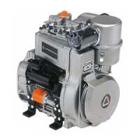
EasyManua.ls Logo

Lombardini 9 LD 626-2 User Manual

Lombardini 9 LD 626-2
88 pages
To Next Page IconTo Next Page
Page #1 background imageLoading...
Page #1 background image
cod. 1-5302-286
9 LD Engine Series
WORKSHOP MANUAL

Table of Contents

Other manuals for Lombardini 9 LD 626-2

Questions and Answers:

Lombardini 9 LD 626-2 Specifications

General IconGeneral
BrandLombardini
Model9 LD 626-2
CategoryEngine
LanguageEnglish

Summary

PREFACE

1 GENERAL REMARKS AND SAFETY INFORMATION

WARRANTY CERTIFICATE

Details the warranty coverage, terms, and conditions for Lombardini engines.

GENERAL SERVICE MANUAL NOTES

Provides guidelines for using genuine parts and understanding data formats.

GLOSSARY AND TERMINOLOGY

Defines key terms used throughout the manual for clarity.

SAFETY AND WARNING DECALS

Explains the meaning of symbols and warnings used in the manual.

SAFETY REGULATIONS

Outlines essential safety rules and precautions for engine operation and maintenance.

GENERAL SAFETY DURING OPERATING PHASES

Covers essential safety practices during engine operation and maintenance procedures.

SAFETY AND ENVIRONMENTAL IMPACT

Discusses the engine's impact on the environment and mitigation measures.

2 TECHNICAL INFORMATION

TROUBLE SHOOTING

Provides a table of common engine problems and their potential causes.

MANUFACTURER AND ENGINE IDENTIFICATION

Details how to find and interpret engine identification plates and data plates.

MAIN COMPONENTS

Illustrates and lists the key components of the LOMBARDINI engine.

TECHNICAL SPECIFICATIONS

Presents detailed technical data and specifications for the engine models.

FUEL SUPPLY CIRCUIT

Details specifications for the fuel system, including filters and pumps.

LUBRICATION CIRCUIT

Provides specifications for the engine's lubrication system.

ELECTRICAL SYSTEM

Lists specifications for alternators and starter motors.

PERFORMANCE DIAGRAM

Presents performance curves (power, torque, consumption) for different engine models.

OVERALL DIMENSION

Shows engine dimensions with a diagram and measurement table.

3 MAINTENANCE - RECOMMENDED OIL TYPE - REFILLING

ROUTINE ENGINE MAINTENANCE

Outlines a schedule of routine checks and operations based on operating hours.

EXTRAORDINARY MAINTENANCE

Highlights specific maintenance tasks after initial hours and oil/filter replacements.

LUBRICANT

Explains SAE classification and international specifications for lubricants.

ACEA Regulations - ACEA Sequences

Lists ACEA sequences for petrol and diesel engines.

API / MIL Sequences

Shows API and MIL sequences for engine oil classification.

PRESCRIBED LUBRICANT

Specifies the recommended lubricant (AGIP Superdiesel Multigrade 10W40) and alternatives.

9 LD ENGINES OIL CAPACITY

Provides the engine oil capacity with and without the oil filter.

FUEL RECOMMENDATIONS

Offers advice on purchasing, storing, and using diesel fuel.

FUEL TYPE

Specifies suitable diesel fuel types and standards for the engine.

FUELS FOR LOW TEMPERATURES

Details winter fuel recommendations for cold weather operation.

BIODIESEL FUEL

Provides guidance on using biodiesel fuels and limitations.

4 DISASSEMBLY / REASSEMBLY

RECOMMENDATIONS FOR DISASSEMBLING AND ASSEMBLING

General guidelines and precautions for engine disassembly and assembly procedures.

RECOMMENDATIONS FOR OVERHAULS AND TUNING

Specific advice for engine overhauls and tuning operations.

AIR CLEANER

Details maintenance and replacement of oil-bath and dry air cleaners.

Dry air cleaner, Donaldson type

Instructions for checking and replacing the Donaldson dry air cleaner cartridge.

Clogging indicator

Explains the function and calibration of the clogging indicator.

Oil vapour separator

Procedure for cleaning and refitting the oil vapour separator.

MANIFOLDS, INTAKE/EXHAUST

Covers checking and replacing gaskets for intake and exhaust manifolds.

EXTERNAL ALTERNATOR CONTROL BELT

Instructions for disassembly, tension check, and reassembly of the external alternator belt.

FUEL TANK

Procedure for removing, emptying, and checking the fuel tank and its components.

Pulley guard - Shroud - Side plates

Details the function and materials of the pulley guard and shroud.

Cooling fan

Instructions for cleaning, checking, and replacing the cooling fan.

Hub

Information on the hub that holds the alternator rotor and cooling fan.

Internal alternator

Procedure for removing and refitting the internal alternator stator and rotor.

Shroud support (Gear cover plate)

Procedure for removing and refitting the shroud support, checking gaskets.

FLYWHEEL

Instructions for removing and refitting the flywheel, including ring gear replacement.

ROCKER ARMS

Details valve/rocker arm clearance adjustment procedure.

Compression release (optional)

Procedure for checking and setting compression release clearance.

Rocker arm assembly

Details components and dimensions of the rocker arm assembly.

INJECTOR

Procedure for cleaning, checking, and refitting injectors.

Injector for EPA and 97/68 CE engines

Specific instructions for mounting EPA and 97/68 CE engine injectors.

Injector projection

How to adjust injector nozzle projection using copper shims.

CYLINDER HEAD

Procedure for tightening cylinder heads and replacing head gaskets.

Valves

Details valve components and procedure for removing half collets.

Valve stem sealing rings - Reassembly

Instructions for lubricating and inserting valve stem sealing rings.

Valve springs

Procedure for measuring and checking valve spring length and load.

Valve material

Specifies the materials used for intake and exhaust valves.

Valve guides and valve guide housings

Details valve guide materials, dimensions, and installation.

Valve guide insertion

Procedure for heating the cylinder head and pressing in valve guides.

Dimensions and clearance between guides and valves

Provides dimensions and clearance specifications for valve guides and valves.

Valve seats and housings

Provides dimensions for valve seats and housings.

Valve seat grinding

Instructions for grinding valve seats and checking recess depth.

Pushrod tube

Checks to perform when refitting the pushrod tube.

CYLINDER

Instructions for checking cylinder roughness and cross-hatch pattern.

PISTON

Procedure for measuring piston diameter and checking for wear.

Piston weight

Guidance on weighing pistons to ensure balance during replacement.

Piston rings - End gaps (mm)

Procedure for measuring piston ring end gaps in the cylinder.

Pistons ringis - Clearance between grooves (mm)

Provides dimensions and limit values for piston ring groove clearance.

Piston rings - Fitting sequence

Outlines the correct sequence for fitting piston rings.

Piston - Refitting

Instructions for connecting the piston to the connecting rod and inserting the piston pin.

Piston clearance

Details how to measure and adjust piston clearance using head gasket thickness.

CONNECTING ROD

Procedure for removing the oil sump and connecting rod cap.

Connecting rod small end bushing

Provides dimensions and clearance for the connecting rod small end bushing.

Connecting rod alignment

Procedure for checking the alignment of connecting rod bores.

Connecting rod weight

Guidance on weighing connecting rods to ensure balance.

Connecting rod big end bearing

Instructions for refitting connecting rod big end bearings.

CRANKSHAFT TIMING GEAR

Procedure for removing and refitting the crankshaft timing gear.

MAIN BEARING SUPPORTS

Instructions for removing and refitting main bearing supports (gear and flywheel sides).

Center main bearing support, locating screw.

Procedure for straightening and unscrewing the locating screw.

Crankshaft removal

Instructions for removing the crankshaft.

Crankshaft center main bearing support

Procedure for refitting the crankshaft center main bearing support.

Crankshaft lubrication ducts

Instructions for cleaning crankshaft lubrication ducts.

Crankshaft journal radius

Specifies the radius of crankshaft journals and the importance of restoring it.

Checking main journals and crank pins

Procedure for checking main journals and crank pins using a micrometer.

Main journal and crank pin diameter

Provides dimensions for main journals and crank pins.

How to measure main bearing inside diameter

Instructions for measuring main bearing inside diameter using a micrometer.

Main bearing and connecting rod big end bearing inside diameter

Provides dimensions for main and connecting rod big end bearings.

Clearance between main journals/crank pins and connecting rod bearings

Specifies clearances and limit values for journals and bearings.

Main bearing supports - Dimensions

Lists dimensions for main bearing supports.

Main bearing housings

Provides dimensions for main bearing housings.

Crankshaft end play

Procedure for checking and setting crankshaft end play.

How to measure camshaft journals and housings

Instructions for measuring camshaft journals and housings with micrometers.

How to measure intake/exhaust cam height

Procedure for measuring intake and exhaust cam height.

Camshaft end play

Procedure for checking camshaft end play using a dial gauge.

CAMSHAFT TIMING

Instructions for timing the camshaft gear with the crankshaft gear.

Valve timing without considering timing marks

Method for setting valve timing without using timing marks.

Valve timing check

Procedure for checking valve timing using a dial gauge and flywheel.

Valve timing - Angles

Defines angles for checking valve timing with specific clearance values.

HYDRAULIC PUMP

Information on hydraulic pump installation.

Hydraulic pump components (1 P)

Lists and illustrates components of the hydraulic pump (1 P).

MECHANICAL SPEED GOVERNOR

Describes the location and type of mechanical speed governor.

Mechanical speed governor components

Lists and explains the components of the mechanical speed governor.

Governor springs with rocker arm system

Details the governor system with rocker arm and its operation.

Governor springs with single-spring system

Describes the governor system with a single-spring setup.

ELECTRONIC SPEED GOVERNOR (optional)

Lists components of the optional electronic speed governor.

Adjustment of the stroke end (STOP):

Procedure for adjusting the stroke end of the stop control.

Adjustment of extra fuel delivery:

Procedure for adjusting the extra fuel delivery setting.

Speed governor wiring diagram

Provides a wiring diagram for the speed governor system.

5 LUBRICATION SYSTEM

LUBRICATION SYSTEM AND BREATHER RECIRCULATION SYSTEM

Overview of the lubrication and breather system and its importance.

Standard lubrication system circuit

Diagram and component list for the standard lubrication system.

Lubrication system with oil radiator circuit

Diagram and components of the lubrication system with an oil radiator.

OIL PUMP

Instructions for checking the oil pump gear teeth and control shaft.

OIL FILTER CARTRIDGE (EXTERNAL)

Details components and characteristics of the external oil filter cartridge.

OIL PRESSURE RELIEF VALVE

Details the oil pressure relief valve and its disassembly/reassembly.

OIL PRESSURE CHECK

Procedure for checking oil pressure with a gauge.

Oil pressure curve with engine at idle speed

Presents the oil pressure curve at idle speed versus temperature.

Oil pressure curve with engine at full speed

Presents the oil pressure curve at full speed versus temperature.

OIL RADIATOR (on request)

Lists components of the optional oil radiator system.

6 FUEL SYSTEM

FUEL FEEDING / INJECTION CIRCUIT

Illustrates fuel feeding/injection circuits with internal and external filters.

Fuel feeding / injection circuit with fuel filter inside the fuel tank

Diagram of the fuel system with an internal fuel filter.

Fuel feeding / injection circuit with external fuel filter

Diagram of the fuel system with an external fuel filter.

Fuel feeding / injection circuit with external fuel filter and double solenoid valve

Diagram of the fuel system with external filter and double solenoid valve.

Fuel feeding / injection circuit with fuel filter inside the fuel tank and double solenoid valve

Diagram of the fuel system with internal filter and double solenoid valve.

FUEL FILTER

Details components and characteristics of internal and external fuel filters.

Fuel filter (inside fuel tank)

Lists components of the fuel filter located inside the fuel tank.

Fuel filter, external

Lists components of the external fuel filter.

FUEL LIFT PUMP

Describes the diaphragm-type fuel lift pump and its manual lever.

Fuel feeding pump components

Lists components and characteristics of the fuel feeding pump.

Piston fuel lift pump (on request)

Details characteristics of the optional piston fuel lift pump.

INJECTION PUMP

Overview of the single-body injection pump and its operation.

Injection pump for Standard and 97/68 CE engines

Lists components of the injection pump for Standard and 97/68 CE engines.

Injection pump for EPA engines

Lists components of the injection pump for EPA engines.

Plunger and Barrel Assembly

Details the plunger and barrel assembly and its interchangeability.

How to check plunger and barrel for internal leakage

Procedure for checking plunger and barrel for internal leakage.

How to check injection pump delivery valve sealing

Procedure to check the delivery valve sealing for proper operation.

Test data for injection pump delivery

Presents test data for injection pump delivery based on engine type.

How to reassemble injection pump components

Step-by-step guide for reassembling injection pump components.

How to mount injection pump on the engine

Procedure for correctly mounting the injection pump onto the engine.

Injection pump/mechanical speed governor timing

Instructions for timing the injection pump and mechanical speed governor.

Injection static advance adjustment

Procedure for adjusting the injection static advance.

Injection advance adjustment

Instructions for adjusting injection advance by adding/removing shims.

INJECTOR

Details on Size S injector and nozzle for standard engines.

Size S Injector, only for standard engines

Lists components of the Size S injector.

Size S Nozzle, only for standard engines

Provides features and cleaning instructions for Size S nozzle.

Size P injector, for 97/68 CE and EPA engines

Lists components of the Size P injector for EPA and CE engines.

Size P nozzle, for 97/68 CE and EPA engines

Provides features and cleaning instructions for Size P nozzle.

Injector setting

Procedure for setting the injector pressure using a calibration pump.

7 ELECTRIC SYSTEM

Electric starting layout with internal alternator

Wiring diagram for electric starting with an internal alternator.

Electric starting layout with external alternator

Wiring diagram for electric starting with an external alternator.

ALTERNATOR

Details of the 12 V, 18A alternator, including dimensions.

Alternator battery charger curve (12 V, 18 A)

Presents the battery charger curve for the 12V, 18A alternator.

Alternator - 24 V, 6 A

Details of the 24 V, 6A alternator, including dimensions.

Alternator battery charger curve - 24 V, 6 A

Presents the battery charger curve for the 24V, 6A alternator.

Alternator - 12 V, 14 A

Details of the 12V, 14A alternator, including dimensions.

Alternator battery charger curve standard - 12 V, 14 A

Presents the battery charger curve for the 12V, 14A alternator.

Magnetization checking tool (Part No. 7000-9727-001)

Instructions for using the magnetization checking tool.

Checking for cable continuity

Procedure for checking cable continuity and insulation.

Alternator, external - 12V, 33 A

Details of the external 12V, 33A alternator and its features.

Alternator battery charger curve - external, 12 V, 33 A

Presents the battery charger curve for the external 12V, 33A alternator.

VOLTAGE REGULATOR

Details of the 12V, 26A voltage regulator and its connections.

How to check voltage regulator for proper operation

Procedure for checking the voltage regulator's operation.

Voltage regulator - 12V, 26A, with "W" terminal

Details of the 12V, 26A voltage regulator with 'W' terminal.

Voltage regulator - 12 V, 30 A

Details of the 12V, 30A bridge-type voltage regulator.

Voltage regulator - 12V, 30A, with "W" terminal

Details of the 12V, 30A voltage regulator with 'W' terminal.

STARTING MOTOR

Information on Marelli and Bosch starting motors.

Bosch starting motor type GIF - 12 V, 1.7 kW

Details of the Bosch 12V, 1.7kW GIF starting motor.

Characteristic curves for starting motor type Bosch - 12 V, 1.7 kW

Presents characteristic curves for the Bosch 12V, 1.7kW starting motor.

Starting motor type Bosch DW (R) 12 V, 1.7 kW

Details of the Bosch DW (R) 12V, 1.7kW starting motor.

Characteristic curves of the 24 V 1.6 kW starting motor

Presents characteristic curves for the 24V, 1.6kW starting motor.

Pre-heating glow plug

Details of the pre-heating glow plug and its voltage/current ratings.

DIRECT STOP ELECTROMAGNETS

Overview of direct stop electromagnets.

Reverse electromagnet - FIRE version

Features and adjustment of the reverse electromagnet (FIRE version).

Direct stop electromagnet

Features and setting procedure for the direct stop electromagnet.

8 SETTINGS

SPEED ADJUSTMENTS

General warning and procedures for adjusting engine speed settings.

Idling speed setting in no-load conditions

Procedure for setting the engine idling speed.

Full speed setting in no-load conditions (standard)

Procedure for setting the engine's full speed.

INJECTION PUMP DELIVERY SETTING

Procedure for setting injection pump delivery using a dynamometric brake.

Injection pump delivery limiting and extra fuel device

Details the injection pump delivery limiting and extra fuel device.

Injection pump delivery setting with dynamometric brake

Step-by-step guide for setting injection pump delivery with a dynamometer.

Injection pump delivery setting without dynamometric brake

Procedure for setting injection pump delivery without a dynamometer.

Required settings (as most commonly applies)

Table of common settings and specific fuel consumption values.

Setting the stop limit stop

Procedure for setting the stop limit stop on the throttle lever.

9 STORAGE

ENGINE STORAGE

Guidelines for protecting engines during storage periods longer than 6 months.

PROTECTIVE TREATMENT

Detailed steps for applying protective treatment for engine storage.

PREPARING THE ENGINE FOR OPERATION AFTER PROTECTIVE TREATMENT

Steps to prepare the engine for operation after storage.

10 TORQUE SPECIFICATIONS AND USE OF SEALANT

Table of tightening torques for the main components

Lists torque specifications and sealant recommendations for major engine components.

Table of tightening torques for standard screws (coarse thread)

Provides torque values for standard coarse thread screws based on resistance class.

Table of tightening torques for standard screws (fine thread)

Provides torque values for standard fine thread screws based on resistance class.

11 SPECIAL TOOLS

Special tools and equipment for maintenance

Lists special tools and their part numbers for engine maintenance.

Related product manuals