EasyManua.ls Logo

LORCH M 2095 - User Manual

LORCH M 2095
12 pages
Print Icon
To Next Page IconTo Next Page
Loading...
910.1053.1-12
Operation Manual
MIG/MAG Welding System
M-Series

Questions and Answers

  • J
    Jordan SmithSep 8, 2025
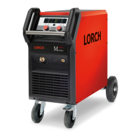
    What causes arc or short circuit between contact tip and gas nozzle in LORCH M 2095?
    • J
      Jason NorrisSep 9, 2025
      An arc or short circuit between the contact tip and gas nozzle in your LORCH Welding System can be caused by spatter build-up inside the gas nozzle. Remove it with special pliers.
  • E
    ethomasSep 12, 2025
    What causes higher wire wear out at wire-feeding unit of LORCH M 2095?
    • L
      Linda McbrideSep 12, 2025
      Higher wire wear out at the wire-feeding unit of your LORCH Welding System can occur if the wire rolls do not fit the wire diameter. Install the correct wire rolls. It can also be caused by incorrect contact pressure at wire feeding; adjust as described in the manual.
  • H
    heatherwilliamsSep 13, 2025
    What to do if there is not sufficient shielded gas in my LORCH M 2095?
    • M
      mtateSep 13, 2025
      If there is not sufficient shielded gas in your LORCH Welding System, it could be due to: * Wrong adjusted quantity of shielded gas: Adjust it correctly as described in the manual. * Dirty pressure reducer: Check the valve. * Torch, gas hose blocked or not airtight: Check and replace if necessary. * Shielded gas being blown away by draught: Avoid draught.
  • G
    gwilliamsSep 15, 2025
    What to do if mains control lamp 40 does not light on LORCH M 2095?
    • G
      Gwendolyn AndersonSep 15, 2025
      If the mains control lamp 40 does not light on your LORCH Welding System, it means that a phase is missing in the mains. Check the machine at another socket and check mains and fuses.
  • B
    Bobby HansenSep 17, 2025
    What to do if the fan of my LORCH M 2095 is not working?
    • A
      Austin FergusonSep 18, 2025
      If the fan of your LORCH Welding System is not functioning, it indicates a missing phase in the mains. Check the machine at another socket and check the mains and fuses.

Summary

Safety Precautions

Transportation

General Regulation of Use

Unit Protection

Noise Emission

Electromagnetic Compatibility (EMC)

Technical Data

Before Operation

Torch Connection

Connect the torch plug into the central socket for operation.

Connecting to the Mains

Plug the unit into the mains socket and ensure correct fusing.

Wire Spool Insertion

Mount the wire coil on the pick-up and adjust the brake.

Wire Electrode Insertion

Thread the wire electrode through the inlet nozzle and central connection.

Ground Cable Connection

Connect the ground cable to the ground connection and workpiece.

Ground Clamp Connection

Fasten ground clamp near the welding location for constant connection.

Connecting the Gas Cylinder

Modifying for Aluminium Welding

Starting Up

Operating Panel Overview

Details on main switch, voltage range, mode selector, step switch, and control knobs.

Mode Selector Switch

Explanation of 2-Stroke, 4-Stroke, and Spot welding modes.

Step Switch Usage

Adjusts welding performance for electrode and material.

Wire-Feed Control Knob

Fine-tunes wire feed speed, automatically adjusted to welding stage.

Spot Welding Control Knob

Adjusts the duration for spot welding operations.

Overload Indicator

Yellow lamp indicates overload; allow unit to cool down.

MIG;MAG Welding Process Basics

Principle of MIG;MAG Welding

Describes arc, wire feed, shielding gas, and filler material.

Types of Arc

Details short circuit, transitional, long, and spray arcs.

Working Range at MAG Welding

Provides data on wire diameter, amperage, and voltage for different arcs.

Principle of MSG-Soldering

Explains MSG-soldering as a low-temperature joining process.

Holding and Manipulating the Torch

Torch Manipulation Positions

Guidance on welding in various positions like horizontal, vertical, and overhead.

Length of the Arc

Explains how arc length affects penetration and bead formation.

Length of the Wire Electrode

Discusses the effect of electrode distance on amperage and penetration.

Care and Maintenance

Troubleshooting

Options

Feed Variant: Steel;Aluminium

Details variations for steel and aluminium feed units (2-roll vs. 4-roll).

Disposal

Service

CE Certificate of Conformity

Publisher

LORCH M 2095 Specifications

General IconGeneral
Protection classIP 23
Mains voltage230 V
Mains frequency50/60 Hz
Current range20-200 A
Welding Current Range20-200 A
Power Supply230 V, 50/60 Hz

Related product manuals