LLR60132/60134_080604 Page 11 of 33
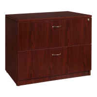
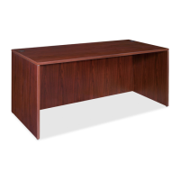
Step 12
Attach the Left and Right Side of
the Drawer Slides (10) to each of
the Keyboard Panel (G) and Print
Panel (H). Secure the Drawer Slides
(10) in place with 12 each 4X14
Screw (8). Note inset drawing of
proper placement of Drawer Slide
on the Keyboard Panel (G) and
Print Panel (H)
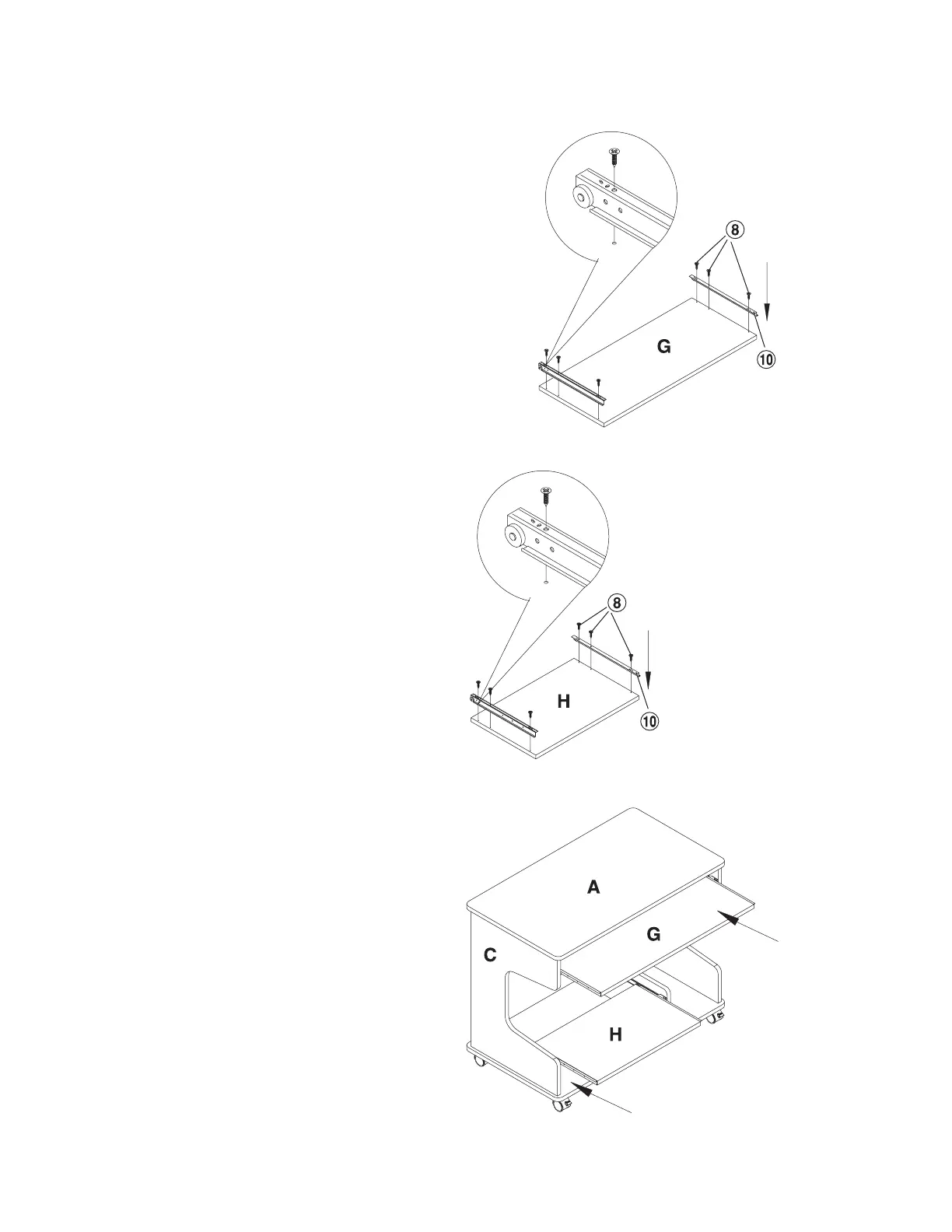
Step 13
Stand the unit to its upright position.
Insert the Print Panel (H) into the
lower set of Case Slide (9).
Insert the Keyboard Panel (G) into
the upper set of Case Slide (9).
Insert the 6 each Cam Cover (3)
onto the exposed Cam Lock (2)
YOU HAVE SUCCESSFULLY
COMPLETED THE ASSEMBLY
OF THIS UNIT!
THANK YOU FOR
PURCHASING THIS ITEM!
Keyboard panel
Print panel
Table panel
Left
side
panel
Keyboard panel
Print panel
 Loading...