LLR44308/44309_081104
Page 9 of 63
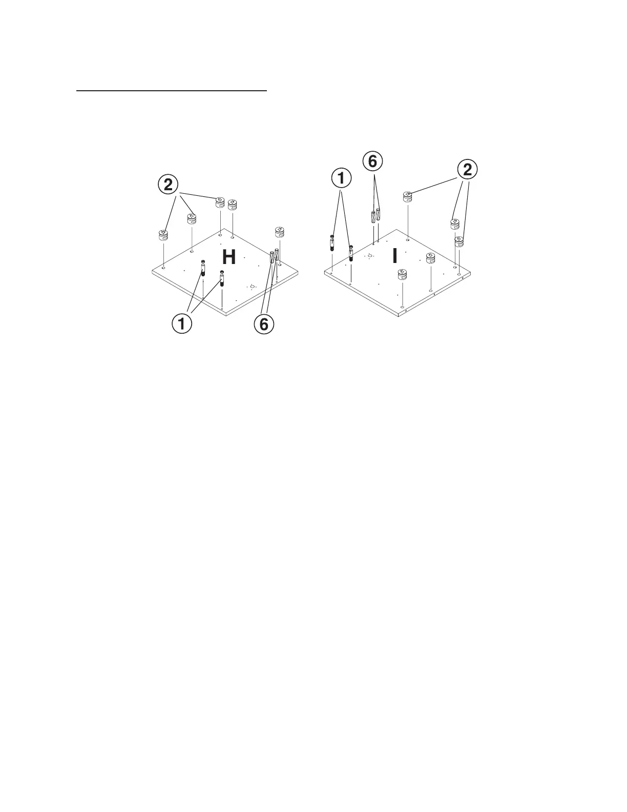
ASSEMBLY INSTRUCTIONS
Step 1
With the Left Mid Panel (H) and Return Mid Panel (I) laying on a non-abrasive surface, insert
10 each Cam Lock (2) (5 in each panel) in the hole position shown on the drawing. When
inserting the cam lock, ensure that the arrow is facing toward the cam screw entry.
With a Rubber Mallet, insert 4 each (2 per panel) in the hole locations shown on the drawing.
With a Phillips Screw Driver, insert 4 each (2 per panel) Cam Screw (1) in the hole locations
shown on the drawing.
Left mid panel
Right mid panel