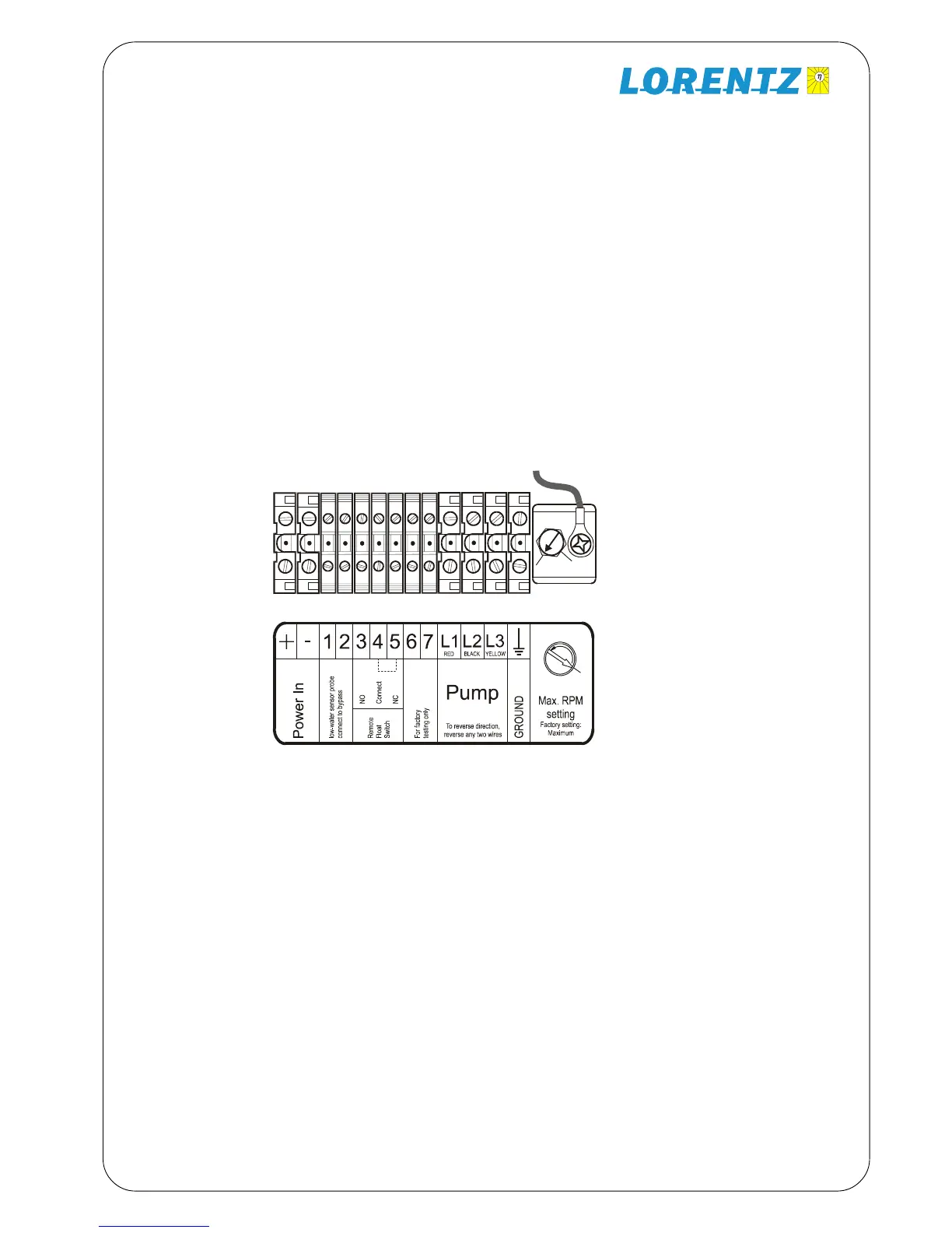
5
Terminals inside the PS-XXX controller.
“Max. RPM setting” is at right. To reduce RPM
turn counter-clockwise
2.4 Electrical Installation-Terminals
Power IN For PV-direct systems, a two-pole discon-
nect switch may be installed between the solar array
and the controller. Switch it off to prevent shock and arc
burn hazard during installation and maintenance, or if
the system will be shut down for the season. For Battery
systems: Connect the controller directly to the plus and
minus terminals of the Battery. Do not connect to the
load terminals of the charger as they may be not strong
enough to provide the starting current. A 20 Amp slow
blow fuse must be installed between. The controller and
the battery.
Ground Connect the ground wire to the ground
connection in the controller. Grounding helps to prevent
shock hazard if there is a fault in the motor.
L1 – L2 – L3 ECDRIVE
®
requires four-conductor (four-
wire) cable between the controller and the motor. The
three wires L1, L2 and L3 carry power. The fourth wire
carries ground. To reverse direction of rotation reverse
any two wires.
No. 1 and 2 In order to protect the pump from being
damaged by dry running connect one well probe cable
to each terminal. If dry run protection is not needed,
short cut these two terminals.
No. 3, 4 and 5 Connect any kind of external switch
(NO or NC type) for remote control of the controller. In
case no switch is used the terminals No. 4 and 5 have
to be connected with a short cable (factory setting). In
case a NO-switch is used (connected to the terminals
No. 3 and 4) the short cable (connecting the terminals
No. 4 and 5) must remain installed.
No. 6 and 7 Connect these two terminals to switch the
controller to battery mode. The motor will be switched
OFF by the controller if the input voltage is below 11 V
for a 12 V battery system and 22 V for a 24V battery
system in order to protect the battery. If the battery
voltage increases to 13 or 26 V the motor will be
switched ON automatically.
PS600 pump systems can be operated from batteries.
Short Circuit protection Install a fuse or circuit breaker
near the power source. For either 48V , use a 20 amp
circuit breaker or a time-delay (slow blow) fuse. The
purpose of this protection is for safety in case of a wiring
fault, and to provide a means of disconnect when install-
ing or maintaining the system. PS600 controllers have
electronic over-current protection against motor overload.
Low-voltage disconnect function. Lead-acid batteries
can be permanently damaged by over-discharge when
the voltage falls below a critical point. To prevent this, the
PS battery-system controller will turn off at low voltage,
and turn back on only after the battery has recovered
significantly. The set points are:
48V SYSTEM: OFF at 44V ON at 48V
A controller in disconnect mode can be reset manually by
turning off/on, but it will quickly disconnect again if the
battery is not gaining a substantial recharge.
2.5 Battery-Based Systems
Wire Sizing for the DC circuit Wire must be sized for
no more than 5% voltage drop at 20 amps (starting).
Refer to a wire sizing chart for 48V, or follow these
examples:
Solar Direct Systems
#10 wire to maximum distance of 30 ft.
Metric: 4 sq. mm to max. 20m
Battery Systems:
#10 wire to maximum distance of 30 ft.
Metric: 4 sq. mm to max. 15m
GREATER LENGTHS For each 150% increase, use
next larger wire size
2.6 Wire Sizing
Manual PS600 BADU Top 12

 Loading...