Controller Installation 3130 Controller Installation
1
1
2
2
3
3
4
4
5
5
6
6
A A
B B
C C
D D
sensor terminals 255-40*
v60°/h30°
v60°/h30°
power terminals 2716-20*
1
1
2
2
3
3
4
4
5
5
6
6
A A
B B
C C
D D
sensor terminals 255-40*
v60°/h30°
v60°/h30°
power terminals 2716-20*
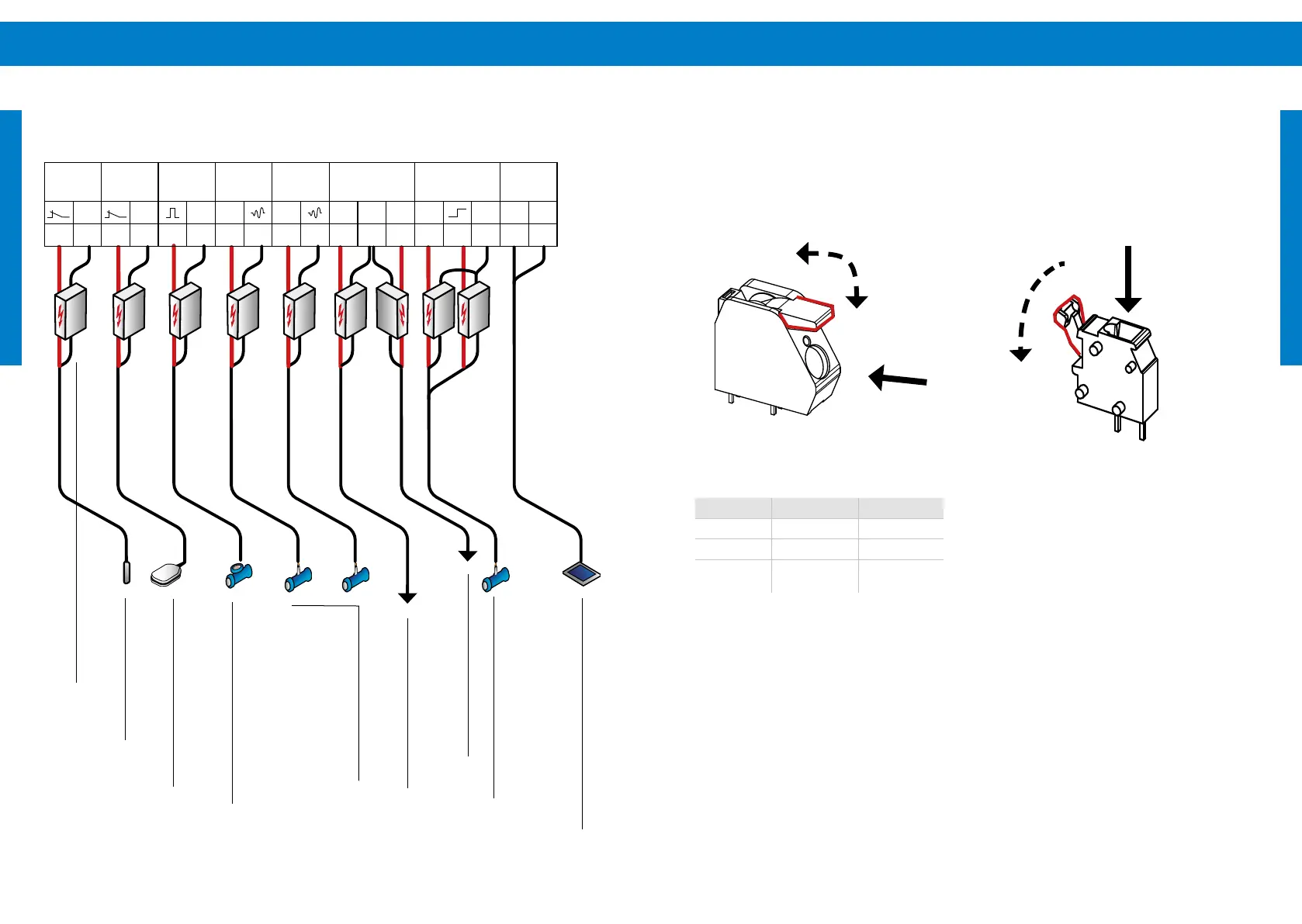
Well
probe
Remote
switch
Water
meter
Analog 1
4-20mA
Analog 2
4-20mA
Relay
Water
sensor
Sun
Sensor
GND GND GND +24V +24V
NC COM NO
+24V GND + –
1 2 3 4 5 6 7 8 9 10 11 12 13 14 15 16 17 18
EN EN
Close
Open
Insert wire
use a at
screwdriver to
push back
Terminal description PSk3
Figure 8: Spring connector for "Solar-IN" and "Motor-
OUT"
Table 4: Clamping range of connectors
Insert wire
Open
Close
Terminal AWG size Metric size
Motor 16 - 6 AWG 1.5 - 16 mm
2
PV 16 - 6 AWG 1.5 - 16 mm
2
Sensor 28 - 12 AWG
0.08 - 2.5
mm
2
Figure 9: Spring connector for "Sensor terminals 1-18
and fan terminal"
Figure 7: Sensor terminal wiring example
Well
probe
Remote
switch Water
meter
Analog
sensors
Out NC
Water sensor
Sun Sensor
Surge
Protector
Out NO