Reference/Direction Sensor
Page 11
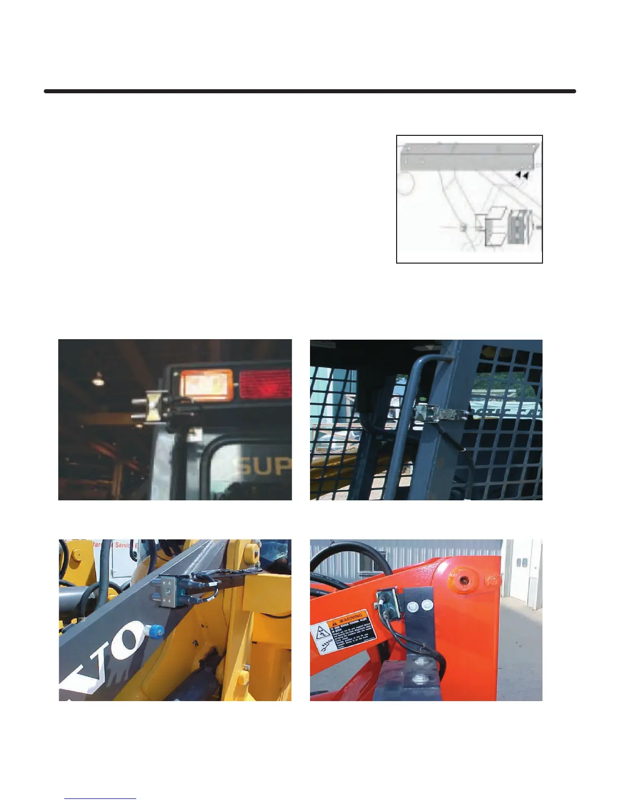
Reference/Direction Sensor Mounting
3. Assemble the Reference/Direction clamp assembly as shown.
The bracket is designed so that the sensor may be installed
on either side of the machine, by rotating the angle bracket 90
degrees.Remove the original M8 bolt from the green nylon clamp,
and replace it with longer M8 x M60 mm. Then tighten with the
sensors in the correct position.The clamp with sensors should
then be inserted into the clamp holder, and tightened into position
using the M8 self-locking nut supplied.The whole assembly can
then be bolted to the angle bracket at the suitable angle for
the specific installation, using the two M6 x 16mm bolts and nuts
provided. Mounting locations vary by machine type shown below
are mounting options.
Skid Steer top rear of cab Skid Steer front of cage
Small Wheel Loader lift arm pivot point Small Wheel Loader lift arm pivot point
 Loading...