Junction Box
Page 16
Remote Enter
Junction Box
The Junction Box provides connections for
the 18 conductor head unit cable, all the
sensors and the power supply.
The Junction Box is not sealed. It should be
located where is will be protected for
excessive moisture and dirt.
1. The Junction Box can be mounted using the
screws provided, or left in-line with the cables.
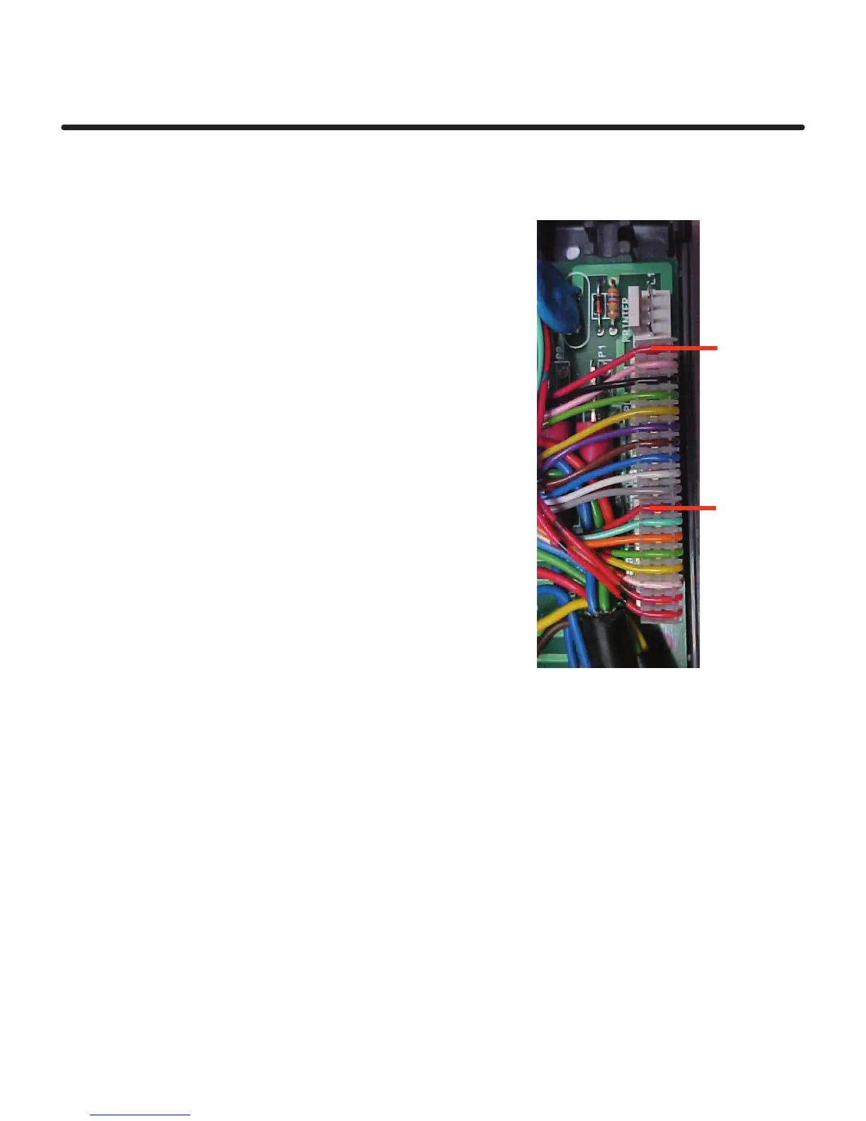
2. Connect the head unit cable onto the PCB
header as shown.
NOTE:The red wire on the 10 way plug goes on
pin 1 of the connector.
The Blue/Red wire on the 8 way plug goes
on pin 11 of the connector.
3. Locate the cable grommet into the groove
in the juction box, cable tie the head unit
lead onto the moulded flange to provide
strain relief.
4. Connect the Sensors. The Wiring Connections
are printed on the lid of the Junction Box.
The connections are also shown in the
appropriate sections in the manual.
Red Wire Pin 1
Red/Blue Pin 11
Note: No means of strain relief
is provided for the sensor
cables. Its recommended
that you cable tie them
securely to prevent strain
on the screw terminal
connections.

 Loading...