I141 I GB PL 10 11 31100027
ATTENZIONE!
Questi apparecchi devono essere installati
da personale qualificato, nel rispetto delle
vigenti normative impiantistiche, allo scopo
di evitare danni a persone o cose.
I prodotti descritti in questo documento
sono suscettibili in qualsiasi momento di
evoluzioni o modifiche. Le descrizioni ed i
dati contenuti in questo documento non
possono pertanto avere alcun valore
contrattuale.
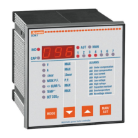
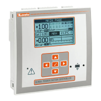
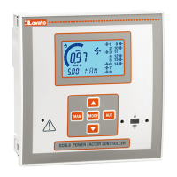
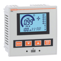
DESCRIZIONE
– Regolatore automatico del fattore di
potenza a microprocessore.
– Display a LED, 3 cifre 7 segmenti.
– Tastiera a membrana 4 tasti.
– Interfaccia seriale TTL-RS232 per set-up
e collaudo automatico mediante PC.
– Sensore di temperatura interno.
– Funzioni avanzate (misura corrente
sovraccarico condensatori, fattore di
potenza medio settimanale,
memorizzazione dei valori massimi).
– 2 relè programmabili come allarme e/o
comando ventilazione.
VERSIONI
DCRK5 contenitore 96x96mm, 5 gradini
DCRK7 contenitore 96x96mm, 7 gradini
DCRK8 contenitore 144x144mm, 8 gradini
DCRK12 contenitore 144x144mm,
12 gradini
INSTALLAZIONE
–
Installare l’apparecchio secondo gli schemi
di connessione riportati a pag. 18-19.
– Per inserzione trifase il T.A. deve essere
connesso sulla fase non
utilizzata per
alimentare l’apparecchio, come indicato
negli schemi di connessione a pag. 18-19.
– L’apparecchio viene fornito predisposto
per il riconoscimento del senso della
corrente del T.A.. In caso di impianti di
cogenerazione è necessario disabilitare
questa funzione (vedere capitolo menù
avanzato) e provvedere alla corretta
connessione del T.A..
– Il secondario del T.A. deve essere
collegato a terra.
WARNING!
This equipment must be installed by
qualified personnel, in compliance with
regulations in force for electrical systems, to
avoid damages or safety hazards.
The pfoducts, illustrated in this document,
are subject to be revised or improved at any
moment. Technical data and descriptions do
not therefore have any contractual value.
DESCRIPTION
– Digital microprocessor power factor
controller
– 3 digit 7 segment LED display
– 4 key membrane keypad
– TTL-RS232 serial interface for set-up and
automatic testing via PC (Personal
Computer)
– Internal temperature sensor
– Advanced functions for capacitor current
overload measurement, average weekly
power factor, maximum value logging
– 2 relays programmable as alarm and/or
fan control.
VERSIONS
DCRK5 5 steps, 96x96mm housing
DCRK7 7 steps, 96x96mm housing
DCRK8 8 steps, 144x144mm housing
DCRK12 12 steps, 144x144mm housing
INSTALLATION
– Install the controller according to wiring
diagrams given on page 18-19.
– For three-phase connection, the CT
(Current Transformer) must be connected
to the free phase, i.e. not
on phases used
to supply the unit, as indicated in the
wiring diagrams on page 18-19.
– The controller automatically recognizes
the CT current flow. In case of
co-generation systems, disable this
function (refer to advanced menu section)
and connect the CT correctly.
– The CT secondary must be
earthed/grounded.
UWAGA!
By uniknąć uszkodzeń i zagrożenia życia,
urządzenia te powinny być instalowane przez
wykwalifikowany personel i w zgodzie z
odpowiednimi przepisami.
Produkty zaprezentowane w poniższym
dokumencie mogą zostać zmienione lub
ulepszone w każdej chwili, bez konieczności
wcześniejszego informowania o tym fakcie. Dane
techniczne i opisy nie mają wartości kontraktowej.
OPIS
– Mikroprocesorowy regulator współczynnika
mocy
– Wyświetlacz LED: 3 cyfrowy, 7 segmentowy
– 4 przyciski funkcyjne
– Interfejs TTL-RS232 do ustawień i kontroli
przez komputer
– Wewnętrzny czujnik temperatury
– Zaawansowane funkcje do pomiaru prądu
przeciążenia kondensatorów, średniego
tygodniowego współczynnika mocy, zapisu
wartości maksymalnych
– 2 wyjścia przekaźnikowe programowalne jako
alarm i/lub sterowanie wentylatora.
WERSJE
DCRK5 5 stopni, obudowa 96x96mm
DCRK7 7 stopni, obudowa 96x96mm
DCRK8 8 stopni, obudowa 144x144mm
DCRK12 12 stopni, obudowa 144x144mm
INSTALACJA
– Należy podłączyć regulator zgodnie ze
schematem podanym na stronie 18 i 19.
– W układzie trójfazowym przekładnik prądowy
musi być podłączony do wolnej fazy, to jest tej,
która nie jest używana do zasilania
urządzenia, jak pokazano na schemacie
podanym na stronie 18 i 19.
– Regulator automatycznie rozpoznaje przepływ
prądu przez przekładnik. W układach
kogeneracji należy wyłączyć tą funkcję
(zobacz menu zaawansowane) i podłączyć
przekładnik we właściwy sposób.
– Uzwojenie wtórne przekładnika koniecznie
musi być uziemione.
LOVATO ELECTRIC S.P.A.
24020 GORLE (BERGAMO) ITALIA
VIA DON E. MAZZA, 12
TEL. 035 4282111
TELEFAX (Nazionale): 035 4282200
TELEFAX (International): +39 035 4282400
E-mail info@
L
ovato
E
lectric.com
Web www.
L
ovato
E
lectric.com
1
DCRK5 - DCRK7 - DCRK8 - DCRK12
I REGOLATORI AUTOMATICI DI RIFASAMENTO
GB AUTOMATIC POWER FACTOR CONTROLLERS
PL AUTOMATYCZNE REGULATORY WSPÓŁCZYNNIKA MOCY