I412 GB I 11 19 31100198
3
MAIN MENU
To access the main menu:
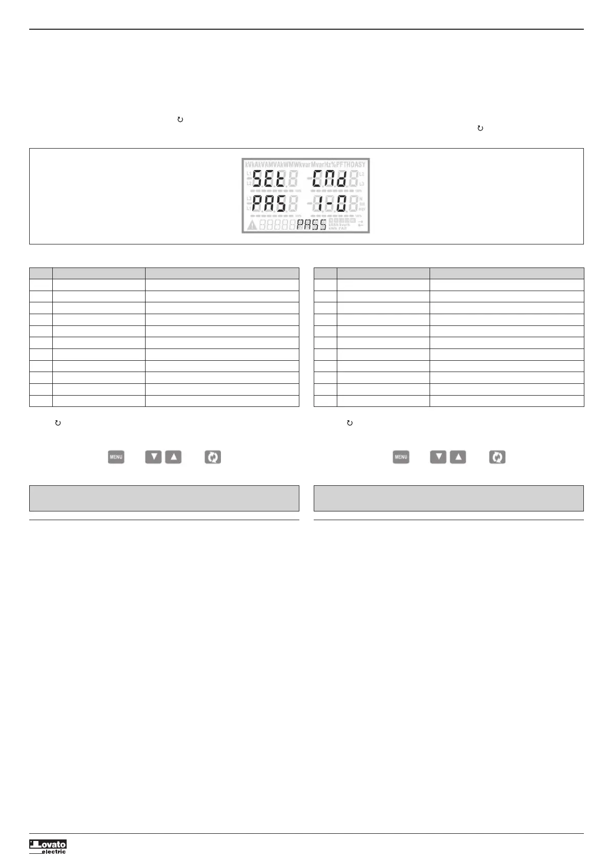
– Press the MENU button. The main menu is displayed (see figure) with the following possible choices:
• SET - Access to the Setup menu settings
• CMD - Access to the command menu
• PAS - Entering the Password
• I-O - I / O expansion status
– The selected choiche flashes. In the alphanumeric disp lay scrolls a written description.
– If you must enter the password, the menu opens with the voice PAS already selected.
– Press
LM
to select the desired item and then press to confirm your choice.
– If you want to return to the measurement display, press MENU again.
MENU PRINCIPALE
Per accedere al menu di principale:
– Premere il tasto MENU. Viene visualizzato il menu principale (vedi figura) con le possibili scelte:
• SET – Accesso al menu impostazioni Setup
• CMD – Accesso al menu comandi
• PAS – Inserimento della password
• I-O – Visualizzazione stato I/O espansione
– La scelta selezionata lampeggia. Nel display alfanumerico scorre una scritta descrittiva della scelta
effettuata.
– Se è necessario impostare la password, il menu si apre con la voce PAS già selezionata.
– Premere
LM
per selezionare la voce volute e poi premere per confermare la scelta.
– Se si vuole tornare alla visualizzazione misure premere di nuovo MENU.
WIRING TEST
– The wiring test allows to verify if the connection of the DMG device has been executed properly.
– To be able to execute the test, the device must be connected to an active plant, with the following
conditions:
• three-phase system with all phases presence (V > 50VAC PH-N)
• current flowing in each phase > 1% of the CT primary.
• positive flow of energies (that is a normal plant where the inductive load draws power from the
supplier).
– To launch test execution, enter command menu and select command C.16 as per Commands menu
instructions.
– The test allows to verify the following points:
• reading of the three voltage phases
• phase sequence
• voltage imbalance
• reverse polarity of each CT
• mismatch between voltage and current phases.
– If the test does not succeed, the display shows the reason of the failure.
TEST DI COLLEGAMENTO
– Il test di collegamento consente di verificare se l’installazione del multimetro è stata effettuata
correttamente.
– Per poter eseguire il test, il multimetro deve essere inserito in un impianto attivo con le seguenti
condizioni:
• sistema trifase con presenza di tutte le fasi (V > 50VAC L-N)
• corrente minima circolante su ciascuna fase> 1% del fondo scala del TA impostato
• verso positivo delle energie (cioè in un comune impianto dove il carico induttivo assorbe energia
dalla fornitura)
– Per lanciare l’esecuzione del test, entrare nel menu comandi e selezionare il comando C.16 secondo le
istruzioni del capitolo Menu comandi.
– Il test consente di verificare i seguenti punti:
• lettura delle tre tensioni
• sequenza delle fasi
• sbilanciamento delle tensioni
• inversione della polarità di uno o più TA
• scambio delle fasi fra tensioni/correnti
– Se il test non viene superato, il display visualizza la ragione dell’errore.
Code MENU DESCRIPTION
P01 GENERAL Detailed data of the installation
P02 UTILITY Language, backlight, display
P03 PASSWORD Access codes enabling
P04 INTEGRATION Readings integration time
P05 HOUR COUNTER Hour counter enabling
P07 COMMUNICATION (COMn) Communication ports
P08 LIMIT THRESHOLDS (LIMn) Limit thresholds on readings
P09 ALARMS (ALAn) Alarm messages
P11 ENERGY PULSING (PULn) Energy pulse count
P13 INPUTS (INPn) Digital inputs
P14 OUTPUTS (OUTn) Digital outputs
– The following table lists the available menus:
– Press to enter the selected menu.
– At this point you can select the submenu (if any) and then the sequential number of the parameter,
always with the function keys as follows:
Backward Increment/decrement Forward
Cod. MENU DESCRIZIONE
P01 GENERALE Dati caratteristici dell’impianto
P02 UTILITA’ Lingua, luminosità, display ecc.
P03 PASSWORD Abilitazione protezione accesso
P04 INTEGRAZIONE Tempi di integrazione misure
P05 CONTAORE Abilitazione contaore
P07 COMUNICAZIONE (COMn) Porte di comunicazione
P08 SOGLIE LIMITE (LIMn) Soglie sulle misure
P09 ALLARMI (ALAn) Messaggi di allarme
P11 IMPULSI (PULn) Impulsi di conteggio energia
P13 INGRESSI (INPn) Ingressi digitali
P14 USCITE (OUTn) Uscite digitali
– Nella seguente tabella sono elencati i menu disponibili:
– Premere per accedere al menu selezionato.
– A questo punto è possibile selezionare il sottomenu (se presente) e poi il numero sequenziale del
parametro, sempre con la funzione dei tasti come segue:
Indietro Incrementa/decrementa Avanti
NOTE: Per i successivi parametri vedi manuale completo scaricabile dal sito.NOTE: For the other parameters, refer to the complete instructions manual available
on the website.
 Loading...