I412 GB I 11 19 31100198
4
PC- DMG610-615 CONNECTION THROUGH RS485 INTERFACE CONNESSIONE PC-DMG610-615 MEDIANTE INTERFACCIA RS485
DMG610-615 n°1DMG610-615 n°31
PX1
SGBTR A
PC
RS485
AB
RS485
AB
120R
TERMINALS POSITION DISPOSIZIONE MORSETTI
Aux supply
100-440V~
50/60Hz
3,5 W
9,5 VA
V Input 100-600V~ 50/60HzI Input 0,025-5A~ RS485
I3
I2
I1
A
VN
V3
V2
V1
B
A2
A1
Aux supply
100-440V~
50/60Hz
3,5 W
9,5 VA
V Input 100-600V~ 50/60HzI Input 0,025-5A~ RS485
I3
I2
I1
A
VN
V3
V2
V1
B
A2
A1
MECHANICAL DIMENSIONS AND FRONT PANEL CUTOUT (mm) DIMENSIONI MECCANICHE E FORATURA PANNELLO (mm)
96
96
92
92
65
55
8.5
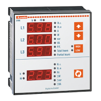
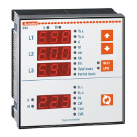
DMG600 DMG610-615
INSTALLATION
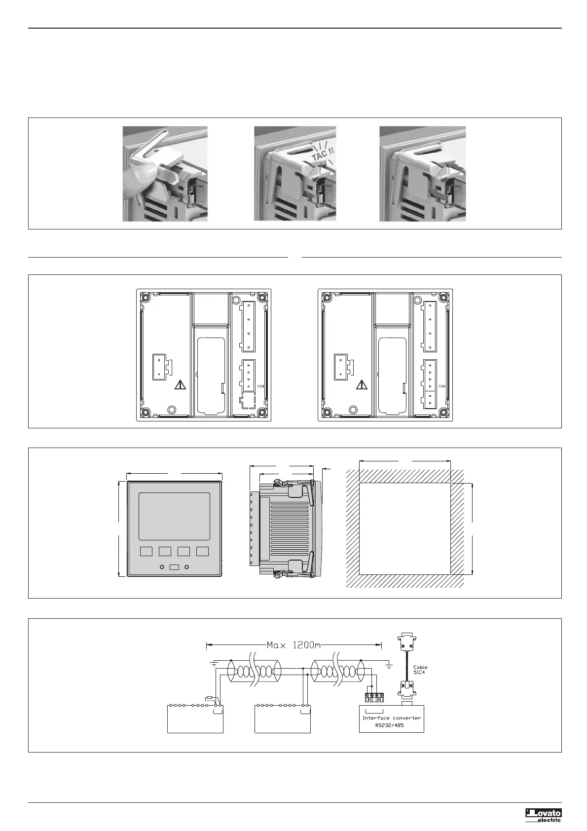
– DMG6... is designed for flush-mount installation. With proper mounting, it guarantees IP65 front
protection.
– From inside the panel, for each four of the fixing clips, position the clip in one of the two sliding
guide, then press on the clip corner until the second guide snaps in.
– Push the clip forward pressing on its side and making it slide on the guides until it presses
completely on the internal surface of the panel.
INSTALLAZIONE
– DMG6... è destinata al montaggio da incasso. Con il corretto montaggio garantisce una protezione
frontale IP65.
– Dall’interno del quadro, per ciascuna delle quattro clips di fissaggio, posizionare la clip in una delle
due guide laterali, premendo successivamente sullo spigolo della clip in modo da agganciare a scatto
anche la seconda guida.
– Spingere la clip in avanti facendo pressione sulle sue pareti laterali e facendole scorrere sulle guide
fino che le apposite alette deformabili premono al massimo possibile contro la superficie interna del
pannello.
– For the electrical connection see the wiring diagrams in the dedicated chapter and the requirements
reported in the technical characteristics table.
– Per i collegamenti elettrici fare riferimento agli schemi di connessione riportati nell’apposito capitolo e
alle prescrizioni riportate nella tabella delle caratteristiche tecniche.



 To Next Page