Do you have a question about the Lowrance Point-1 and is the answer not in the manual?
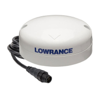
Illustrates the process and dimensions for surface mounting the GPS antenna.
Shows the recommended path for routing the cable when surface mounting.
Provides visual guidance for pole mounting the antenna using an external cable.
Details the steps for pole mounting the antenna with an internal cable connection.
Offers guidance on selecting an optimal mounting spot to minimize interference.
Outlines receiver type, channels, update rate, and accuracy for the GPS sensor.
Covers operating temperatures, splash proof rating, humidity, and power requirements.
Step-by-step instructions for calibrating the heading sensor via vessel turns.
Explains how to calibrate the heading sensor using a compatible multifunction display.
Guidance on configuring the network when multiple heading sensors are present.
Provides detailed measurements and thread specifications for mounting.
Illustrates the NMEA 2000® network connection and lists relevant PGNs.
Details the sensor's role in chart stabilization, course over ground, and radar overlay.
Lists the directives and standards the product conforms to for regulatory compliance.
Cautionary note advising against unauthorized modifications that could void operating authority.
| Type | GPS Antenna with Heading Sensor |
|---|---|
| NMEA 2000 | Yes |
| Heading Sensor | Yes |
| Update Rate | 10 Hz |
| Waterproof Rating | IPX7 |
| WAAS/EGNOS/MSAS | Yes |
| Integrated Compass | Yes |
| Compass | Yes |
| Pitch and Roll | Yes |
| Connector | NMEA 2000 Micro-C |
| Compatibility | NMEA 2000 |
| Accuracy | 3 meters |
| Current Draw | 200 mA |
| Operating Temperature | -25°C to +55°C (-13°F to 131°F) |
| Dimensions | 90 mm diameter |
| Weight | 0.25 kg (0.55 lbs) |