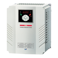
iP5AiP5A
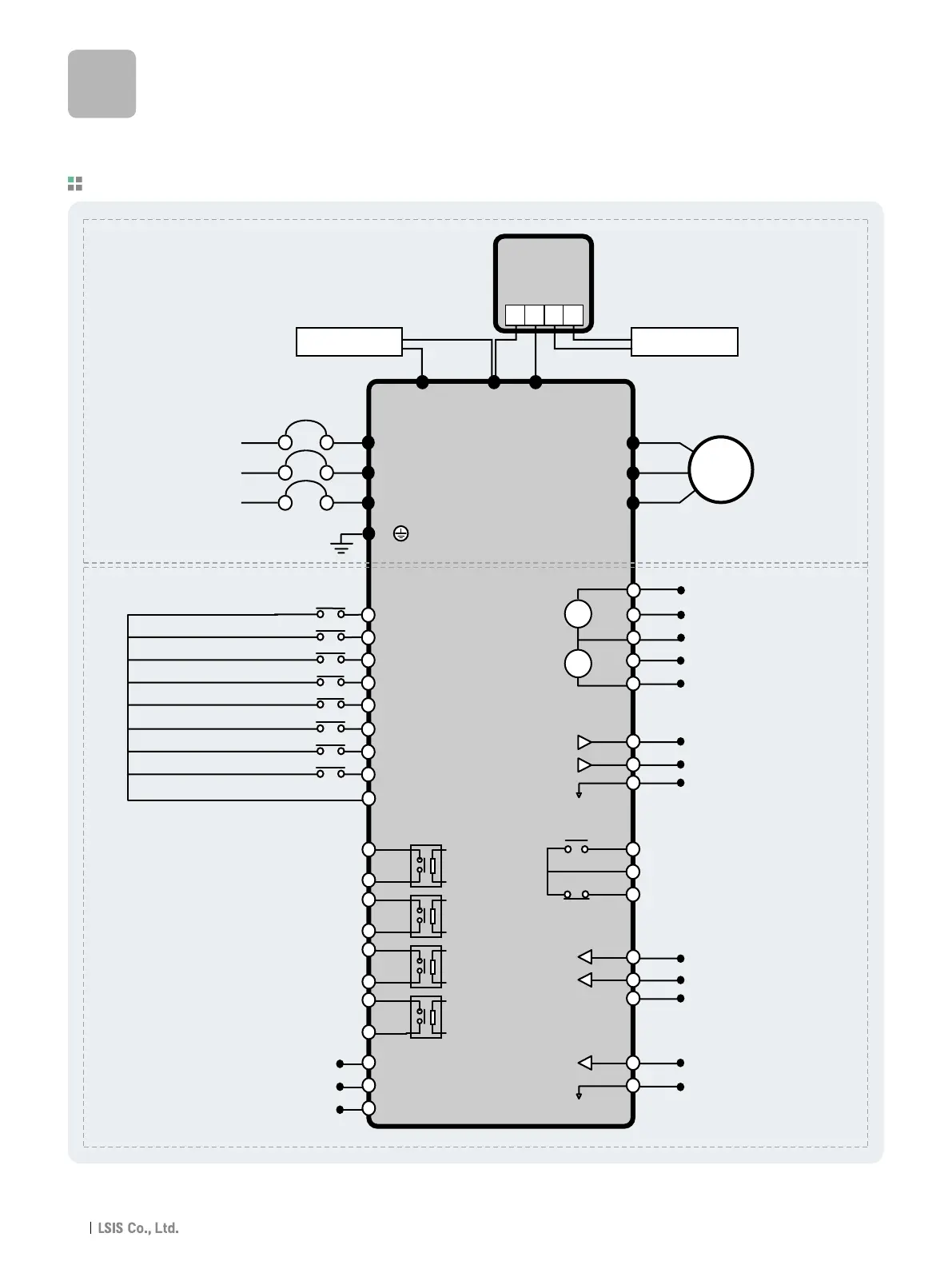
Wiring
Note 1) 5G is Common Ground for Analog Meter Output (SO, S1) and External motor thermal detection (ET). CM is Common Ground for Analog input.
2) Use terminal V1 for V1, V1S (0~12V, -12~12V) input.
3) To add DC reactor, remove DC Bus Choke and connect to P1(+), P2(+).
4) SA, SB terminal is provided with 600V class model only.
For 37~90kW (50~125HP) / 315~450kW (400~600HP)
M1
M2
M3
M4
M5
M6
M7
M8
CM
Programmable Digital Input 1 (Speed L)
Programmable Digital Input 2 (Speed M)
Programmable Digital Input 3 (Speed H)
Fault Reset (RST)
Drive Disable (BX)
Jog Frequency Reference (JOG)
Forward Run Command (FX)
Reverse Run Command (RX)
Common Terminal
Fault Contact Output
less than AC250V (DC30V), 1A
Frequency Reference (Pulse: 0~100kHz)
Common for Frequency Reference (Pulse)
External Motor Thermal Detection
MCCB (Option)
R (L1)
S (L2)
T (L3)
G
U
V
W
Main Power Circuit
Dynamic
Braking Unit
(Optional)
DB Unit (Optional)
DB Resistor
DC Bus Choke
(Optional )
Control Circuit
DC Bus Choke DB Resistor
3
Ø
AC Input
50/60 Hz
Motor
A1
C1
A2
C2
A3
C3
A4
C4
C-
C+
CM
ET
5G
A0
B0
CM
3A
3C
3B
S0
S1
5G
V+
V1
CM
I
V-
+
-
+
-
P1 (+)
P N B1 B2
P2 (+) N (-)
RS485 Signal
RS485 Common
Programmable Digital Output
Output Frequency Meter
Output Voltage Meter
Common for Output Meter Signal
Analog Power Source (+12V)
Frequency Reference (0~12V, V1S: -12~12V)
Frequency Reference Common Terminal
Frequency Reference (0~20mA or 4~20mA)
Analog Power Source (-12V)
14