Industrial Drive for Fan and Pump STARVERT iP5A
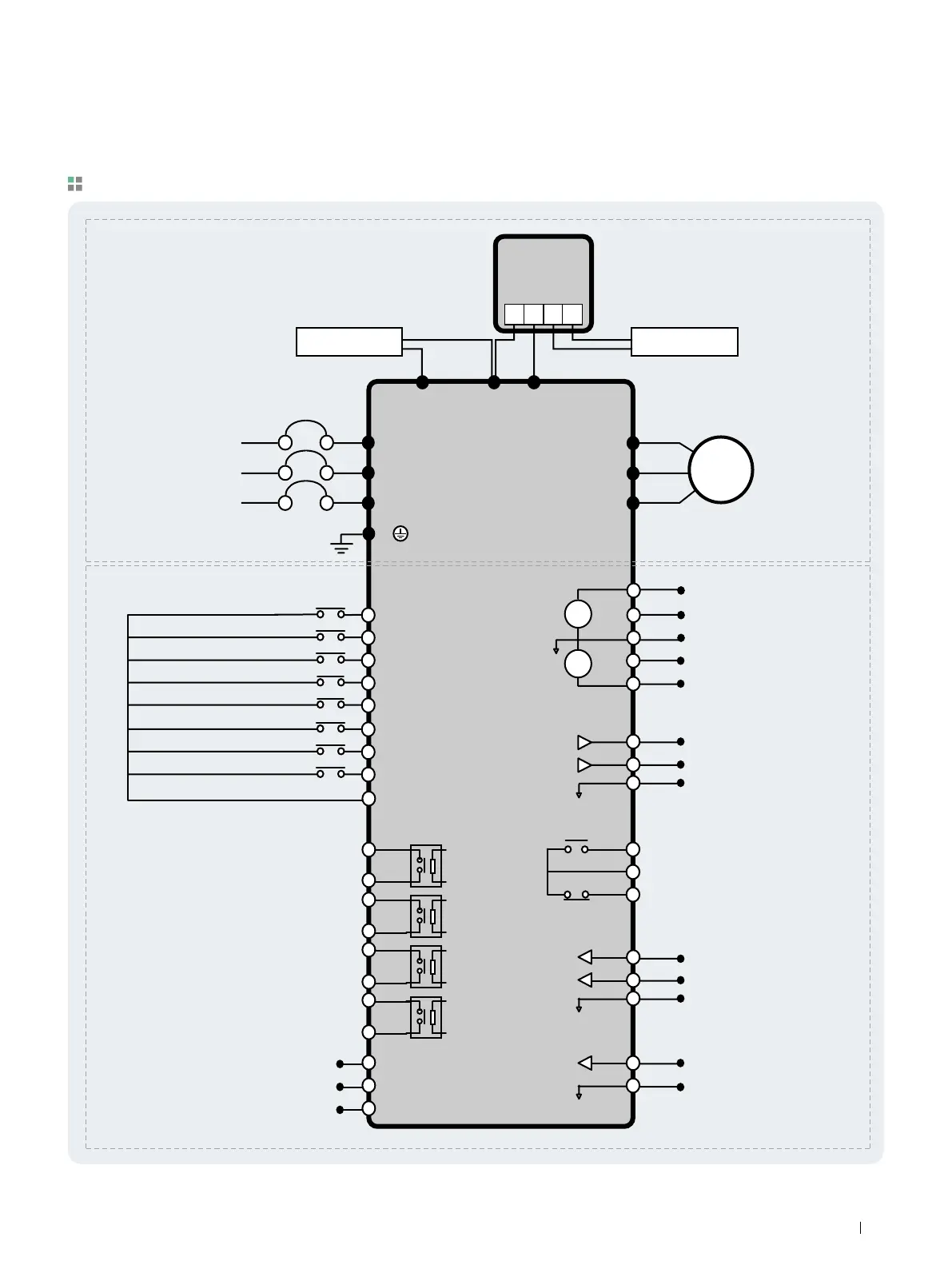
Note 1) 5G is Common Ground for Analog Input / Output. (Only applied to 0.75 ~ 30kW products)
2) Use terminal V1 for V1, V1S (0~12V, -12~12V) input.
3) To add DC reactor, Remove DC Bus Choke and connect to P1(+), P2(+).
4) SA, SB terminal is proovided with 600V class model only.
Wiring
M1
M2
M3
M4
M5
M6
M7
M8
CM
Programmable Digital Input 1 (Speed L)
Programmable Digital Input 2 (Speed M)
Programmable Digital Input 3 (Speed H)
Fault Reset (RST)
Drive Disable (BX)
Jog Frequency Reference (JOG)
Forward Run Command (FX)
Reverse Run Command (RX)
Common Terminal
Analog Power Source (+12V)
Frequency Reference (0~12V, V1S: -12~12V)
Frequency Reference Common Terminal
Frequency Reference (0~20mA or 4~20mA)
Analog Power Source (-12V)
Fault Contact Output
less than AC250V (DC30V), 1A
Frequency Reference (Pulse: 0~100kHz)
Common for Frequency Reference (Pulse)
External Motor Thermal Detection
MCCB (Option)
R (L1)
S (L2)
T (L3)
G
U
V
W
Main Power Circuit
Dynamic
Braking Unit
(Optional)
DB Unit (Optional)
DB Resistor
DC Bus Choke
(Optional)
Control Circuit
DC Bus Choke DB Resistor
3
Ø
AC Input
50/60 Hz
Motor
A1
C1
A2
C2
A3
C3
A4
C4
C-
C+
CM
NT
5G
A0
B0
5G
3A
3C
3B
S0
S1
5G
V+
V1
5G
I
V-
+
-
+
-
P1 (+)
P N B1 B2
P2 (+) N (-)
RS485 Signal
RS485 Common
Programmable Digital Output
Output Frequency Meter
Output Voltage Meter
Common for Output Meter Signal
For 0.75~30kW (1~40HP)
13
Drive Starvert iP5A Series