Video Intercom Main Unit·Quick Start Guide
7
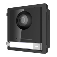
Figure 3-1 DIP Switch
2. Set the sub module address according to the DIP rules, and install the rubber cover
back.
Digit 1, 2, 3, 4 are used to coding the sub module address; Digit 5, 6, 7 are reserved;
Digit 8 is a resistance (120Ω) is you set it as on.
Valid sub module address range is 1 to 8. The No. should be unique for sub modules
that connected to the same main unit.
The sub module address and corresponding switch status as below.
3.2 One-Module Installation
3.2.1 One-Module Surface Mounting
Mounting Frame
 Loading...