TECHNICAL DETAILS
INSTALLATION
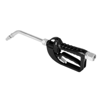
1. Control valve is 1/2" oil inlet, when
connecting with hose fitting, please
remember to apply the Teflon for
better seal
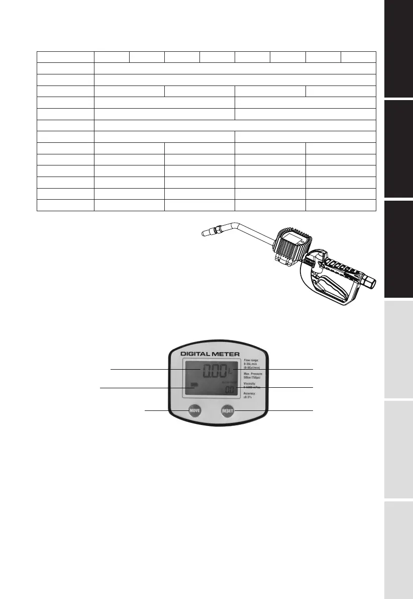
METER
1. 5-digital liquid crystal display for both volume each time and total
2. 4 units: L, GAL, PT and QT
3. Accurate to the second decimal place
4. Low battery indicator
5. 2 buttons: “Move”, “Reset”
DETAILS OF OPERATION
1. BEFORE PUTTING INTO OPERATION
• Check the technical data of the installation match with those of the lube meter. For example
connections, pressure, flow range and medium. Use the formula: Proper correction factor =
(actual value / displayed value) x current correction factor to decide the right connection
factor, then set the proper correction factor (refer to 3. Button usage part)
• Once the meter has been installed, please make sure that no air pressure shocks or particles
can damage the meter
• Please check all connections to avoid leakage
E1
TECHNICAL
DETAILS
EXPLODED AND
PARTS LIST
INSTALLATIONMAINTENANCE
DETAILS OF
OPERATION
TROUBLE
SHOOTING GUIDE
Item No.
Inlet connection
Fluid Range
Pressure Range
Temperature
Precision
Viscosity
Power source
Rigid tube
Flexible hose
Manual tip
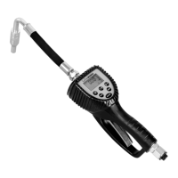
Automatic tip
Digital meter
Note
18063521 18063531 18163521 18163531
1/2”
1~35L/M(0.3~9.25gpm)
0.5-100bar / 7-145psi
5-100Bar / 70-145psi
0.5-50bar / 7-725psi
5-50Bar / 70-725psi
Min. -10°C Max. 60°C Min. -10°C Max. 60°C
■
—
■
—
—
NPT/BSP
—
■
—
■
—
NPT/BSP
■
—
■
—
■
NPT/BSP
—
■
—
■
■
NPT/BSP
--
8-5000mps
±0.5%
1x3V CR2 battery
--
18063526 18063536 18163526 18163536
Attn: Do not apply the meter as a measuring tool for commercial trading
Volume each time
Move Reset
Four Units
Total Volume
Low battery indicator