Installation Instructions
6 | Page
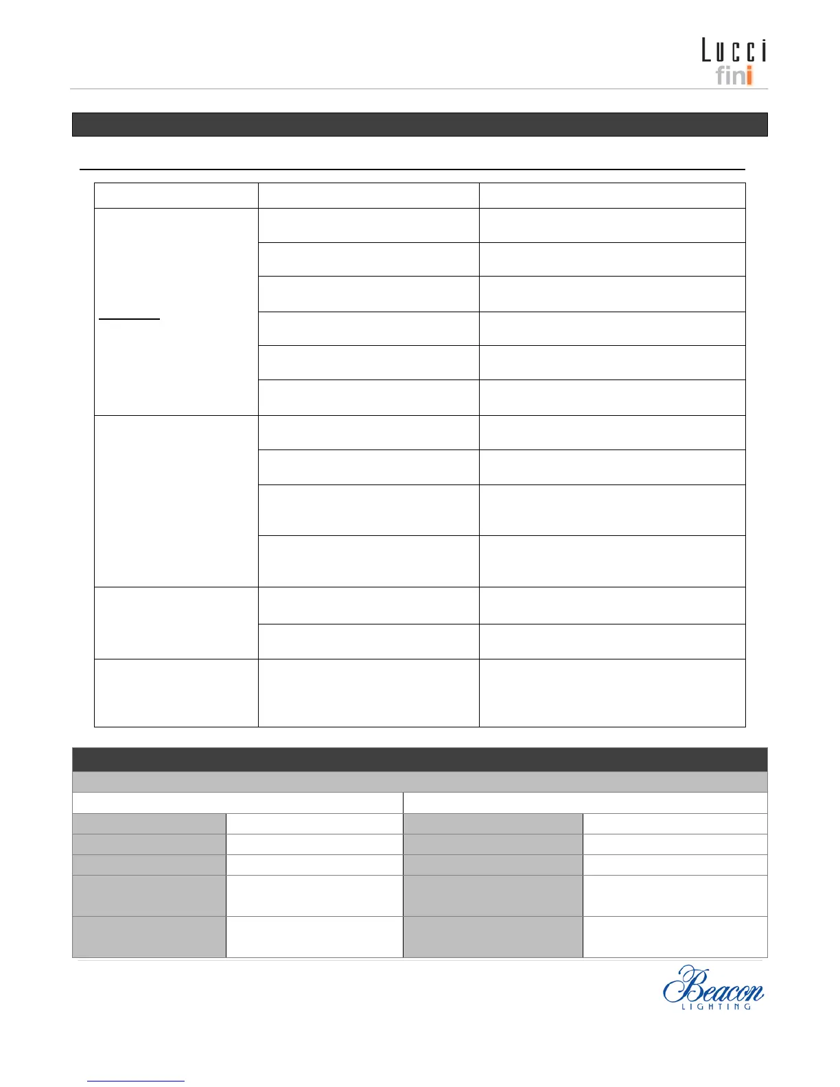
Troubleshooting
Warning: For your safety, ensure the power is switched OFF before starting the troubleshooting procedures
Specifications
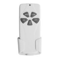
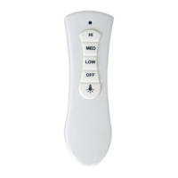
Model No UC7070T Model No UC7076R
Rated Voltage 1x9V battery Rated Voltage 240VAC 50Hz. 70mA
Frequency 433.92MHz Max. Motor 0.5A
Max. Incandescent/halogen
load
300W
Max. Fluorescent lamp &
ballast load
300W
TROUBLE PROBABLE CAUSES SUGGESTED REMEDY
1
No functions operate
Warning: Some task can
only to be performed by a
qualified technician.
Main power not restored
Replace fuse. Turn ON circuit breaker. Turn
ON wall switch.
Wall controller is not removed and
interferes with remote operation.
Remove the fan wall controller, and
replace with ON/OFF switch for remote
Wall switch power to the fan
Switch wall switch ON, to power the
Receiver wiring incorrect.
Verify wiring connections according to
label and wiring diagram.
Transmitter and receiver DIP
switches do not match
Set transmitter and receiver to same DIP
switch setting.
The remote is too far from the
Move closer to receiver
2. Remote LED/LCD no
display
Battery too weak
Replace with all new batteries. Do not mix
up the old and new battery.
Battery at wrong polarity Reinstall the battery at right polarity
The contacts in battery
compartment are corroded or bent.
Clean corroded contacts.
Bend contacts back to their correct
Poor contact with batteries.
Roll the batteries to well sit in the
r replace with other brand
batteries.
3. Operates only at close
range
Signal blocked from reaching
Extend antenna out from canopy, or move
Replace with all new batteries. Do not mix
up the old and new battery.
4. More than one fan
operates interference at
same area.
RF interference
C
hange DIP switch settings to a different
code. Each pair of transmitter and receiver
must have unique DIP switch code.
 Loading...