6
Connect the analog outputs as required in your studio. These connectors deliver a balanced
output signal from a simulated grounded center-tap source. For unbalanced use, either float pin 3
at the 8824 (preferred), or if necessary, connect it to pin 1 at the 8824.
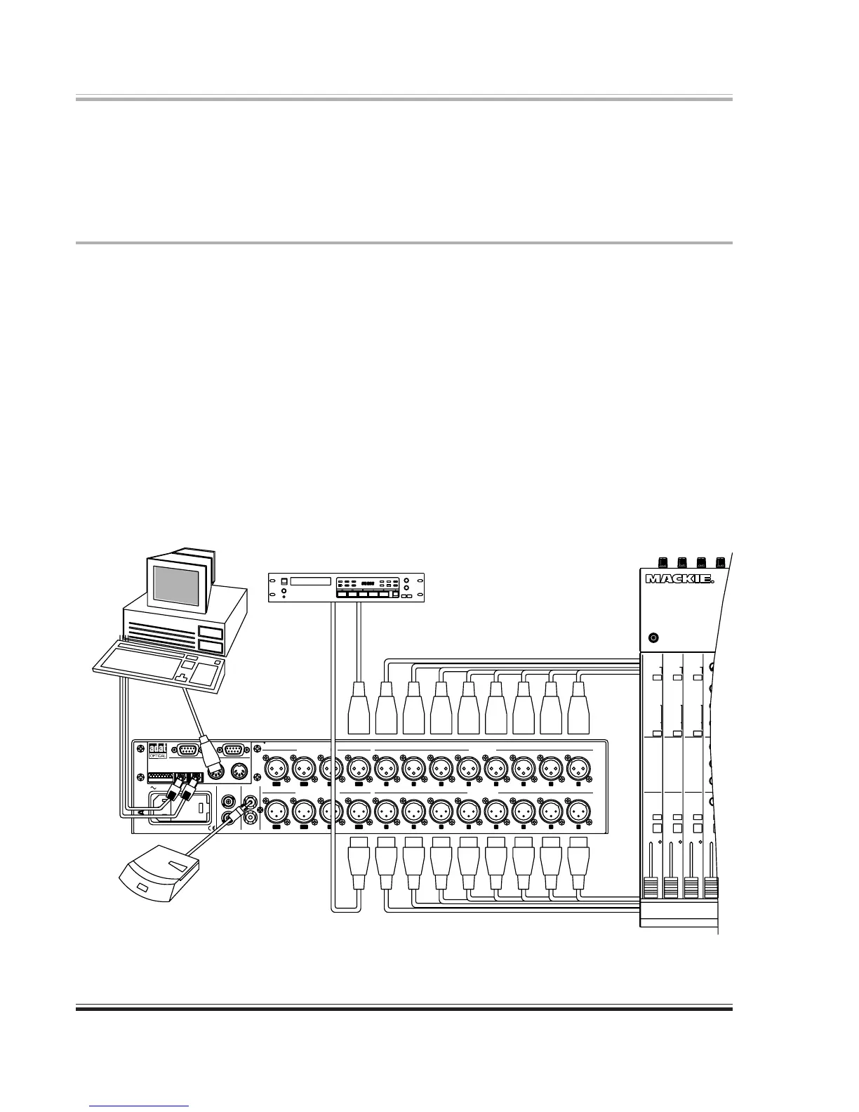
Digital I/O Connections
It is not necessary to connect to any or all of these connectors at any given time. The connectors
used or not used depends on your specific application. In most situations, connect the sources
and destinations that you do have to the 8824. You can then use it as a ‘router’ to patch your
sources, destinations, and the computer workstation software together.
Connect the AES/EBU input connectors to AES/EBU digital audio sources. Connect the AES/
EBU output connectors to AES/EBU digital audio inputs. If you plan to sync to an AES input,
be sure to use inputs 1-2, 3-4, or 5-6, but not 7-8.
Connect the S/PDIF connectors to consumer audio digital inputs.
Connect the Word Clock input connector to a source of digital audio word clock.
Connect the Word Clock output connector to any other unit requiring the word clock signal.
50Hz-60Hz AC INPUT 40 WATTS MAX.
ADA8824
CONFIGURATION
REFER TO USER’S GUIDE
7 8
7 8
5643
5 643
21
21
FOR OPTIONS
INPUT
TO AES OUTPUT
OF PROFESSIONAL
DAT RECORDER
OF PROFESSIONAL
DAT RECORDER
FROM AES OUTPUT
FROM OUTPUT OF
CONSUMER DAT RECORDER
CD PLAYER OR
S/PDIF IN
INPUT OUTPUT
REMOTE CONTROL
COMPUTER FOR
MIDI OUT FROM
OPTICAL
QUIPPED
TO ADAT
I/O CARD
FROM ADAT
EQUIPPED
OPTICAL
I/O CARD
ANALOG AUDIO OUT TO MIXER OR OTHER DESTINATION
ANALOG AUDIO OUT FROM MIXER OR OTHER SOURCE
115V
RISK OF FIRE, REPLACE ONLY WITH SAME TYPE FUSE.
CAUTION: FOR CONTINUED PROTECTION AGAINST
ANALOG INPUTS
ANALOG OUTPUTS
OUT
MIDI
INPUT OUT/THRU
AES/EBU DIGITAL INPUTS
INPUTINPUT
OUT/THRU
OUTPUT
AES/EBU DIGITAL OUTPUTS
S/P DIF
WORD CLOCK
IN
ADAT OPTICAL
OUTPUT
SYNC
ADAT
1
1
2346785
4328765
1-23-45-67-8
5-6 3-4 1-27-8
Figure 3-1. Computer Connections
 Loading...