7
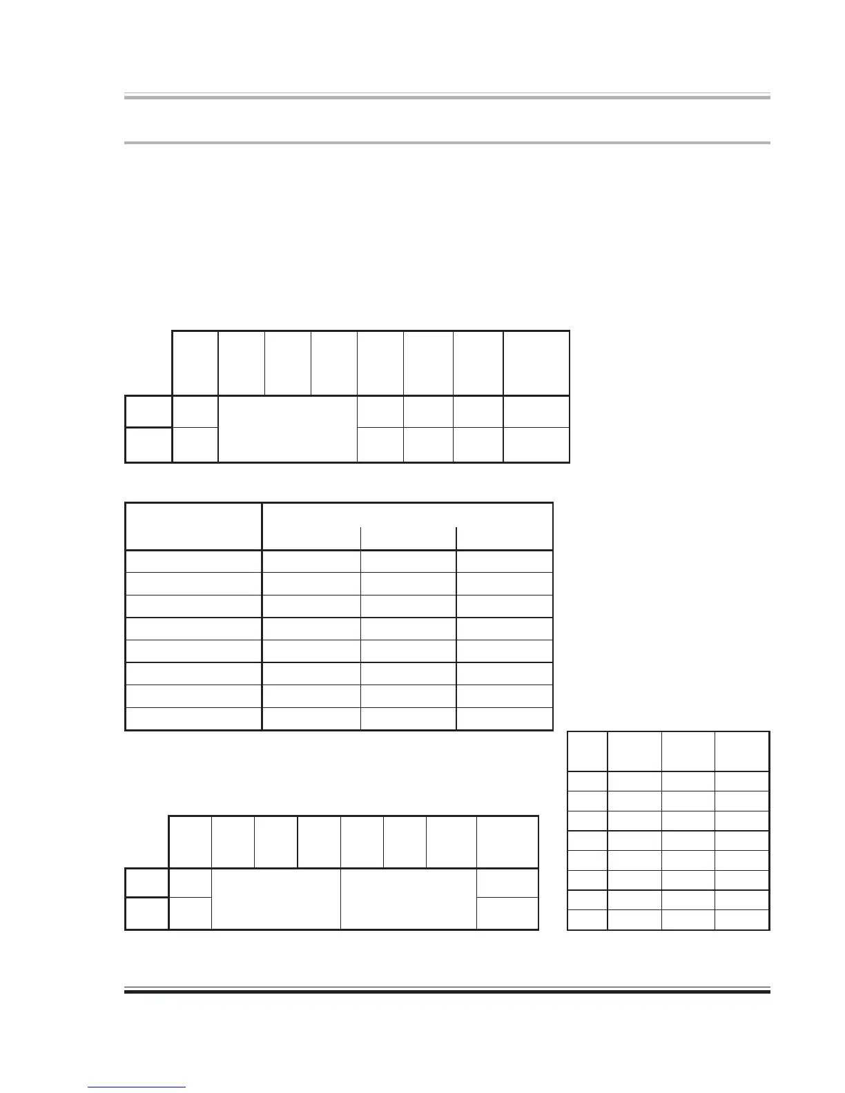
Table 1. Dip Switch Settings in Local mode (SW1 up at power-up).
Table 2. Clock Selector Switch Settings
cnyStupnInoitisoPwSpiD
ecruoS)2WS(0leSklC)3WS(1leSklC)4WS(2leSklC
lacitpOTADA
NWODNWODNWOD
tupnIkcolCdroW
PUNWODNWOD
kcolczHk1.44lanretnI
NWODPUNWOD
kcolczHk84lanretnI
PUPUNWOD
1tupnISEA
NWODNWODPU
2tupnISEA
PUNWODPU
3tupnISEA
NWODPUPU
tupnIFIDP/S
PUPUPU
Configuration Settings
The rear-panel configuration switches determine the initial conditions (power-up) of the 8824.
For most applications use Remote mode (set SW1 down). Set SW2 thru SW4 as required by the
input selection and clock source. Refer to Table 2.
SW5-8 have different functions depending on the mode selection (SW1). In Local mode, these
switches determine the origins of the various output signals and the monitoring point for the
meters. Refer to Table 1. In Remote mode, the arithmetic sum of the bit values of these switches
(SW5-7) sets the MIDI device number (0-7). SW8 switches the MIDI command input between
the ADAT Sync input and the DIN-5 MIDI input connectors. Refer to Table 3.
1WS2WS3WS4WS5WS6WS7WS8WS
/lacoL
etomeR
0leSklC1leSklC2leSklC
golanA
tuptuO
ecruoS
UBE/SEA
tuptuO
ecruoS
lacitpO
tuptuO
ecruoS
tceleSreteM
PU
lacoL
eeS
2elbaT
SEAgolanASEAtuptuO
NWOD
etomeRTADATADAgolanAtupnI
1WS2WS3WS4WS5WS6WS7WS8WS
/lacoL
etomeR
A/NA/NA/N0eciveD1eciveD2eciveD
tupnIIDIM
tceleS
PU
lacoL
A/N
eeS
cnySTADA
)tupnI(
NWOD
etomeR4elbaTIDIM
Table 3. Dip Switch Settings in Remote mode
(SW1 down at power-up).
eciveD
5WS6WS7WS
DI
0eciveD1eciveD2eciveD
0
NWODNWODNWOD
1
PUNWODNWOD
2
NWODPUNWOD
3
PUPUNWOD
4
NWODNWODPU
5
PUNWODPU
6
NWODPUPU
7
PUPUPU
Table 4. Device ID selection.
 Loading...