Models 375 (Including Series One), 375/1, 375/2 & 375/4 Section 3
Ludlum Measurements, Inc. Page 3-2 May 2017
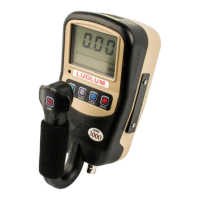
DET Fail: indicated by a red light and an audible tone greater than 68 dB
at 6.1 ft (2 m) for conditions of detector overload, no count from
detector or instrument failure
Low Bat: indicated by a yellow light, beginning when two hours of
battery life remain
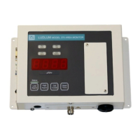
Connector: series ˝C˝ (others available)
Ethernet (optional): 10 Base-T connection for use with Ludlum software
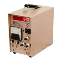
Calibration Controls: accessible from the front of instrument (protective
cover provided)
High Voltage: adjustable from 450-2500 volts
Dead Time: adjustable to compensate for dead time of the detector and
electronics (can be read on the display)
Overload: a display reading of -OL- and audible FAIL alarm indicate
detector saturation. It is normally set to initiate just above the highest
range of the detector.
Over-range: A display reading of ˝----˝ and activated low and high alarms
indicate that the radiation field being measured has exceeded the counting
range of the instrument (or when dead time correction accounts for more
than 75% of the displayed reading).
Data Output: A 9-pin connector with female sockets provides five-
decade log output, RS-232 output, signal ground connection,
FAIL and
HIGH ALARM signals (current sink), and direct connection to battery and
ground
Relays: A 9-pin connector with male pins provides connection to three
fail-safe form C relays, activated by the LOW ALARM (alert) High
ALARM, and instrument FAIL. These contacts are potential-free (non-
powered), but can handle 125 Vac at 0.3 A or 30 Vdc at 1 A.
RS-232 Output: a 2-second dump for computer data logging
Remote (optional): Ludlum Model 271 or 272 remote units
 Loading...