Models 375 (Including Series One), 375/1, 375/2 & 375/4 Section 2
Ludlum Measurements, Inc. Page 2-1 May 2017
Getting Started
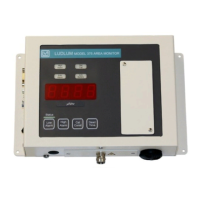
he Model 375 Digital Wall-Mount Area Monitor is designed for
ease of use. This section of the manual is designed to help the first-
time user get started. Initial power-up and basic features of the
Model 375 will be discussed in this section. Other sections of the
manual provide more detailed information.
External Detector (Option)
Warning!
Potential electrical shock hazard - Do not touch the center
pin of the detector connector unless the unit has turned off
and power has been removed for at least one minute.
The Model 375 comes equipped with either an internal detector or a
connector for use with an external detector. If your Model 375 is equipped
with a connector on the bottom side of the chassis, an external detector is
required. If you have an external detector, use the cable provided to connect
it to the Model 375.
Note:
Splicing or re-terminating cables must be done carefully.
Improper termination will result in the “shorting out” of the
detector voltage, a DET FAIL, and/or blown-fuse condition.
Power Up
Plug the wall-mount 9 Vdc power supply into a suitable wall (Mains) outlet.
Sectio
2
T
 Loading...