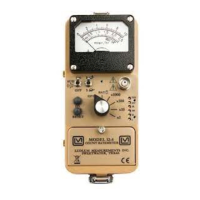
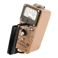
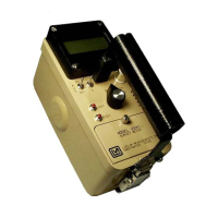
Model 14C Survey Meter
Ludlum Measurements, Inc. Page 18 July 2022
METER DRIVE
The meter is driven by the collector of Q1, coupled as a constant current source in conjunction with
pin 1 of U10. For battery test, U18A opens and U18B closes, and the meter movement is directly
coupled to the battery through R31.
FAST/SLOW TIME CONSTANT
For slow time constant, C7 is switched from the output of the meter drive to parallel C8.
LOW VOLTAGE SUPPLY
Battery voltage is coupled to U16 and associated components (a switching regulator) to provide 5
volts at pin 8 to power all circuits.
HIGH VOLTAGE SUPPLY
On the HV power supply circuit board, high voltage is developed by C1-T1 and rectified by voltage
multiplier CR1–CR6. Output voltage increases as R8 decreases.
High voltage is coupled back through R6 to pin 8 of U1. R7/R8 completes the high voltage, circuit
to ground. High-voltage output is set by R8. During stable operation, the voltage at pin 8 of U1
will stabilize at approximately 1.2 volts.
OVERLOAD
The cathode of V1 is connected through R3 to ground. With R3 on the main board fully clockwise
and the instrument in a 2 R/hr radiation field, voltage at the cathode ranges from 0.2 to 0.4 volts,
depending on exact high-voltage setting and the internal tube.
The cathode voltage is conducted from the HV power supply board through P1 to pin 4, U11 on
the main circuit board. Comparator U11 is biased at 0.22 volts. When pin 4, U11 exceeds 0.22 volts,
U3B switch is closed, grounding R39, causing high-current flow through R38 and causing the meter
circuit to drive full scale.
LOW BATTERY ALARM
When the battery voltage drops to 2.2 volts, Pin 2 of U16 causes U5A switch to open, allowing Pin 3
of U17 to go high. The audio will make a continuous noise.
SWITCHING
All switching, except FAST/SLOW and audio ON/OFF, is accomplished with analog switches. Switch
schematics are shown enabled, although typically, only one switch is enabled at any given time.
 Loading...