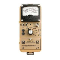
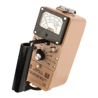
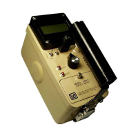
Model 14C Survey Meter
Ludlum Measurements, Inc. Page 17 July 2022
8. Technical Theory of Operation
INPUT
The external detector pulses are coupled from the detector through C4 to amplifier U9/U15/Q2.
CR1 protects the amplifier from input shorts. R40 couples the detector to the high-voltage supply.
The internal detector (V1) is located on the HV Power Supply circuit board. V1 pulses are coupled
through C6 to comparator U13 on the main circuit board. R46 and R47 set the comparator level to
approximately 0.5 volts. R9 on the HV power supply circuit board limits the detector current. With
the range selector switch on ×1K, U5B is closed, coupling high-range pulses to the counting
circuitry.
The internal detector is used only when the range switch is in the ×1K position. In the ×0.1, ×1,
×10, and ×100 ranges, the external detector is used. When the range selector switch is on the 1K
position, Q4 is saturated, blocking external detector pulses.
AMPLIFIER
A self-biased amplifier provides gain in proportion to R43/C11 divided by R41 for the external
detector. Transistor (pin 3 of U9) provides amplification. Pin 2 and 5 of U15 are coupled as a
current mirror to provide a load for pin 3 of U9. The output self-biases to 2 Vbe (approximately 1.4
volts) at emitter of Q2. This provides just enough bias current through pin 2 of U9 to conduct all of
the current from the current mirror.
Positive pulses from emitter of Q2 are coupled to the comparator U12.
DISCRIMINATOR
Comparator U12 provides discrimination. The discriminator is set by the voltage divider, R9 and
R25, coupled to pin 3 of U12. The comparator trip point is approximately 0.16 volts. U12 pulses are
coupled to pin 5 of U7A for meter drive and pin 12 of U7B for audio.
AUDIO
Discriminator pulses are coupled to univibrator pin 12 of U7B. Front-panel audio ON/OFF selector
controls the reset at pin 13 of U7B. When ON, pulses from pin 10 of U7B turn oscillator U17 on.
Pin 5 of U17 drives the can-mounted unimorph. Speaker tone is set by R49, C20 duration by R48,
C16.
DIGITAL ANALOG CONVERTER
Pins 2, 3, and 5 of U8 are coupled as a current mirror. For each pulse of current through R36, an
equal current is delivered to C8. This charge is drained off by R38. The voltage across C8 is
proportional to the incoming count rate.
SCALE RANGING
Detector pulses from the discriminator are coupled to univibrator, pin 5 of U7A. For each scale, the
pulse width of pin 6 of U7A is increased by a factor of 10 with the actual pulse width being
controlled by the front-panel calibration controls and their related capacitors. This arrangement
allows the same current to be delivered to C8 by one-tenth of a count on the ×0.1 range, as 10
counts on ×100 range.
 Loading...