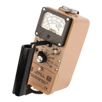
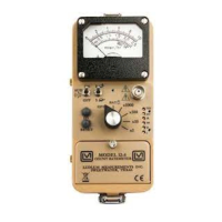
Model 19 MICRO R METER Technical Manual Section 7
Ludlum Measurements, Inc. Page 7-1 February 2012
Technical Theory of Operation
Detector
The detector consists of a crystal of sodium iodide with Thallium activation
(NaI Tl) that gives off light pulses when penetrated by radiation photons.
The light pulses are converted to electrical pulses by the photo cathode of
the photomultiplier tube. The photomultiplier includes a nine-stage electron
amplifier. This amplifier utilizes an electrostatic field for each stage, adding
up to a required 500 to 1500 V supply.
Input
Detector pulses are coupled from the detector through C6 to the amplifier.
CR1 protects the amplifier from input shorts. R37 couples the detector to
the high-voltage supply.
Amplifier
A self-biased amplifier provides gain in proportion to R15 and C4 divided by
R14. Transistor (pin 3 of U4) provides amplification. U6 is configured as a
current mirror to provide a load for pin 3 of U4. The output self biases to 2
Vbe (approximately 1.4 volts) at emitter of Q1. This provides just enough
bias current through pin 3 of U4 to conduct all of the current from the
current mirror.
Positive pulses at R16 are coupled to the discriminator through C5.
Discriminator
Comparator U8 provides discrimination. The discriminator is set by the
voltage divider, R21 and R23, coupled to pin 3 of U8. U8 output pulses are
coupled to pin 5 of U9A for meter drive and pin 12 of U9B for audio.
 Loading...