10
22.5
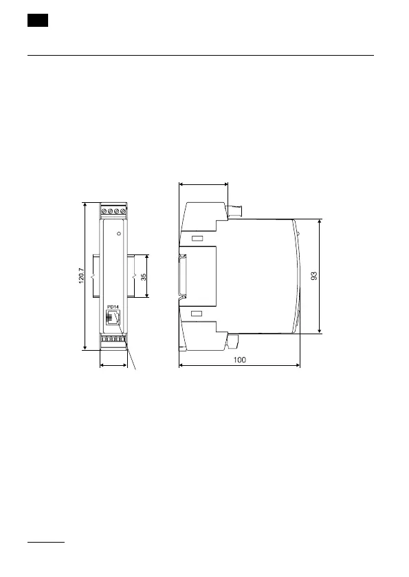
2. INSTALLATION
2.1. Fitting way
P20 transducers are designed to be mounted on a 35 mm rail accor-
ding to EN 60715.
Housing dimensions are: 22.5 x 120 x 100 mm.
On the transducer outside, there are screw or self-locking terminal strips,
which make possible the connection of external wires with a 2.5 mm
2
cross-section (supply and output) and up to 1.5 mm
2
(input).
Connector of the PD14 programmer
Fig. 1. Overall dimensions and fitting way of the transducer
Transdusers should be mounted on the rail in direct contact with an-
other devices that emit heat (eg transducer P20). You must keep a mini-
mum 5 mm distance between the devices to allow emit heat from the
housings to the ambient. Otherwise, the in rated operating temperature
of transducer which is in direct contact with the other transducer may
exceed the rated operating temperature stated operating conditions.
EN
 Loading...