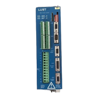
Verstärkermodul / Amplifier Module
CD_..1 / CD_..2
Nr. / No.: 181-00383
01.2003 61
Flußregler 4.2.2.8.1-8
(nur bei Asynchronmaschinen)
Mit den Parametern v
p_psi
(4.2.2.8.1 (0.01-1.00))
und T
n_psi
(4.2.2.8.2 (0.1- 50ms)) läßt sich der
Flußregler optimieren.
Es gelten die gleichen Aussagen wie für den
Stromregler (Parameter v
pi
und T
ni
), d.h. der
Flußregler wird auch über seine Sprungantwort
optimiert.
Die Zustandsgrößen des Flußreglers können nicht
über den Standardmonitor ausgelesen werden.
Die Parameter 4.2.2.8.3-5 lassen sich dem
Typschild des Motors entnehmen oder aus
dessen Daten wie folgt berechnen.
Nennmagnetisierungsstrom (4.2.2.8.3):
I = I *
1 - cos
1 + cos
mr n
ϕ
ϕ
n
n
Die Angabe erfolgt in Prozent bezogen auf den
Gerätemaximalstrom
(s. Kap. 1 „Technische Daten“).
Nenndrehzahl (4.2.2.8.4)
Die Nenndrehzahl ist dem Typschild des Motors
zu entnehmen (0.0-9000.0min
-1
).
Rotorzeitkonstante (4.2.2.8.5)
T =
I - I
r
n
2
mr
2
mr rω
mit dem Nennschlupf
ω π = 2 f
n - n
r n
s n
s
Die Rotorzeitkonstante wird in Millisekunden
angegeben (10-2000ms).
I
n
= Nennstrom des Motors
f
n
= Nennfrequenz des Motors
n
s
= synchrone Drehzahl
n
n
= Nenndrehzahl, (Menüpunkt 4.2.2.8.4)
cosϕ = Nenn-Leistungsfaktor
Die vom Verstärkermodul zur Verfügung gestellte
Spannung reicht bei hohen Frequenzen nicht
mehr aus um die Streuinduktivitäten mit hohem
Strom zu beaufschlagen. Das heißt eine
Stromreduktion ab einer bestimmten Drehzahl ist
erforderlich.
Flux regulator 4.2.2.8.1-8
(only with asynchronous machines)
The flux regulator can be optimized by the parameters
v
p_psi
(4.2.2.8.1 (0.01-1.00)) and T
n_psi
(4.2.2.8.2 (0.1-
50 ms)).
The same instructions as to the current regulator apply
(v
pi
and T
ni
), i.e. the flux regulator is also optimized
through its jump reaction.
The state variables of the flux regulator cannot be read-
out through the standard motor.
The parameters 4.2.2.8.3-5 are stated on the motor
nameplate and can be calculated from its data as
follows.
Nominal magnetizing current (4.2.2.8.3)
I = I *
1 - cos
1 + cos
mr n
ϕ
ϕ
n
n
The data is given in percent related to the unit max.
current, see chap. 1 „Technical Data“.
Nominal speed (4.2.2.8.4)
The nominal speed is stated on the motor nameplate
(0.0-9000.0 rpm)
Rotor time constant (4.2.2.8.5)
T =
I - I
r
n
2
mr
2
mr rω
with nominal slippage
ω π = 2 f
n - n
r n
s n
s
The rotor time constant is given in milliseconds (10-2000
ms).
I
n
= Nominal current of the motor
f
n
= Nominal frequency of the motor
n
s
= Synchronous speed
n
n
= Nominal speed (menu 4.2.2.8.4)
cosϕ = Nominal output factor
With high frequencies the voltage placed at disposal by
the amplifier module is no longer sufficient to connect
the leakage inductances to high current. I.e. from a
defined speed a current reduction is required.