3-12
CDA3000 Operation Manual
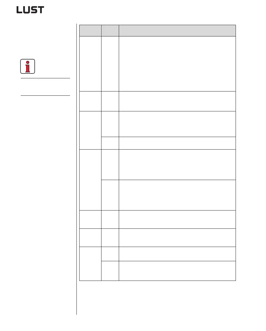
3 Electrical installation
3.7.2 Specification
of control
terminals
Des. Specification
Analog
inputs
ISA00
ISA01
• ISA00: U
IN
= +10 V DC,
±
10 V DC, I
IN
= (0) 4-20 mA DC,
switchable by software
• ISA01: U
IN
= +10 V DC
• Tolerance U:
±
1% v. M., I:
±
1% v. M.
• 24 V digital input, PLC-compatible (IEC1131)
• Switching level Low/High: <4.8 V / >8 V DC
• Resolution 10-bit
•R
in
=110k
Ω
• Floating against digital ground
Analog
output
OSA00 • Tolerance U: ± 2.5 % v.M.
•U
out
=+10 V DC, R
OUT
=100
Ω
•I
max
=5 mA, short-circuit proof
Digital
inputs
ISD00
ISD01
ISD02
ISD03
• PLC-compatible (IEC1131)
• Switching level Low/High: <5 V / >12 V DC
•I
max
at 24 V = 10 mA
•R
IN
= 3 k
Ω
ENPO • Power stage enable = High level
• Specification as ISDxx
Digital
outputs
OSD00 • Short-circuit proof
• PLC-compatible (IEC1131)
•I
max
= 50 mA
• Protection against inductive load
• High-side driver
OSD01 • Short-circuit proof with 24V supply from inverter module
• PLC-compatible (IEC1131)
•I
max
= 50mA
• No internal freewheeling diode; provide external protection
• High-side driver
Relay out-
put
OSD02 • Relay 48 V / 1 A AC, changeover contact
• Usage category AC1
• Operating delay approx. 10 ms
Motor
tempera-
ture
PTC1/2 • Max. 12 V DC, measuring range 100
Ω
- 15 k
Ω
• Suitable for PTC to DIN 44082 or temperature sensor KTY84, yel-
low, or thermostatic circuit-breaker
Voltage
supply
+10.5V • Reference voltage U
R
=10.5 V DC, short-circuit proof
•I
max
= 5 mA
+24V • Auxiliary voltage U
V
= 24 V DC, short-circuit proof
•I
max
= 200 mA (overall, also includes the driver currents for out-
puts OSDox)
The terminal scan
cycle is 1 ms.