Do you have a question about the Lutron Electronics AM-4206M and is the answer not in the manual?
Details circuit, display, measurement units, sensor structure, memory, and power off functions.
Lists electrical specifications for air velocity, air flow, and air temperature ranges, resolution, and accuracy.
Electrical specifications for air velocity measurement including range, resolution, and accuracy.
Electrical specifications for air flow measurement including range, resolution, and area settings.
Electrical specifications for air temperature measurement including measuring range, resolution, and accuracy.
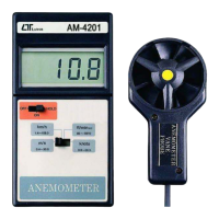
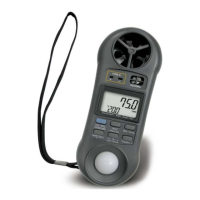
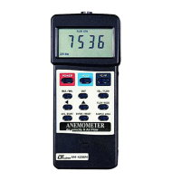
Describes the main display unit of the anemometer, including dual function display capabilities.
Details the button used to turn the anemometer on and off.
Explains the function of the button that freezes the current measurement on the display.
Describes the button for switching between Celsius and Fahrenheit temperature units.
Covers the button for recording and recalling maximum and minimum measured values.
Details the button used to select different measurement units for velocity and flow.
Explains the button used to switch between air velocity and air flow measurement modes.
Describes the button to select different air flow modes: Instant, 2/3 V.max, or Average.
Details the button used to start the averaging process for the AVG mode.
Explains the button for confirming settings or resetting measurements and modes.
Describes the button to input and set the cross-sectional area for air flow calculations.
Identifies the connection point for the anemometer's external probe.
Details the output port for connecting the anemometer to a PC via RS232.
Locates the compartment and cover for the instrument's battery.
Step-by-step guide on how to set up and perform air velocity measurements using the anemometer.
Detailed instructions for performing air flow measurements, including sample area setup and flow modes.
| Model | AM-4206M |
|---|---|
| Manufacturer | Lutron Electronics |
| Category | Measuring Instruments |
| Type | Anemometer |
| Air Temperature Range | 0 to 50°C |
| Data Hold | Yes |
| Memory | No |
| Power Source | 9V battery |
| Display | LCD |
| Air Velocity Accuracy | +/- (2% + 0.2 m/s) |
| Resolution | 0.1 m/s |
| Units | m/s, km/h, ft/min, knots, mph |
| Sensor Type | Vane |
| Accuracy | +/-(2% + 0.2 m/s) |