EasyManua.ls Logo

Lutron Electronics LRF2-OCR2B-P-WH User Manual

Lutron Electronics LRF2-OCR2B-P-WH
6 pages
To Next Page IconTo Next Page
Page #1 background imageLoading...
Page #1 background image
Ceiling
®
SPECIFICATION SUBMITTAL Page
Job Name:
Job Number:
Model Numbers:
Radio Powr SavrTM Wireless Occupancy/Vacancy Sensor
369480g 1 10.31.14
Radio Powr SavrTM Wireless
Occupancy / Vacancy Ceiling Sensor
Lutron® Radio Powr SavrTM occupancy/vacancy sensors
are wireless, battery-powered, passive infrared (PIR)
sensors that automatically control lights via RF
communication to compatible dimming and switching
devices. These sensors detect the heat (IR radiation of
9.5μm) from people moving within an area to determine
when the space is occupied. The sensors then wirelessly
transmit the appropriate commands to the associated
dimming and switching devices to turn the lights on or off
automatically. They combine both convenience and
exceptional energy savings potential along with ease of
installation.
Features
Wireless occupancy sensor has 3 settings available:
Auto-On/Auto-Off, Auto-On Low-Light/Auto-Off, and
Manual-On/Auto-Off
Auto-On Low-Light feature will turn lights on automatically
only if there is less than approximately 10Lux (1fc) of
ambient light
Vacancy-only model available to meet California (U.S.A.)
Title 24 requirements
Uses Clear Connect® technology
Passive infrared motion detection with exclusive Lutron®
XCTTM Technology for fine motion detection
360˚ coverage ranges from 324 ft
2
(30.2 m
2
) to 676 ft
2
(62.4 m
2
), depending on mounting height
Simple and intuitive adjustments available for Timeout,
Auto-On, and Activity settings
Supports advanced occupancy features, such as
dependent occupancy groups and customizable
occupied/unoccupied presets in some systems
Multiple sensors can be added for extended coverage.
Refer to product specification submittal of receiving device
to determine system limits
Lens illuminates during test mode to verify ideal locations
Multiple ceiling-mount methods available for different
ceiling materials
Front accessible test buttons make programming easy
10-year battery life design
RoHS compliant
Models Available
• LRF -OCR2B-P-WH
Color Code
Occupancy and Vacancy
Frequency/Channel Code
• LRF2-VCR2B-P-WH
Vacancy Only
Available for Channel Code 2 Only
Frequency/Channel Codes
Available
2 = 431.0 437.0 MHz (U.S.A., Canada, Mexico, Brazil)
3 = 868.125 869.850 MHz (Europe, U.A.E.)
4 = 868.125 868.4755 MHz (China, Singapore)
5 = 865.5 866.5 MHz (India)
6 = 312.3 314.8 MHz (Japan)
7 = 433.05 434.79 MHz (Hong Kong, Macau)
Color Code
WH = White
Compatible RF Devices
For use with Lutron® products only
Communicates to various wireless Lutron® systems*
* Contact Lutron® Customer Service at www.lutron.com for frequency/
channel code compatibility with your particular geographic region, and for
integrating with other Lutron® lighting and shading products.
Question and Answer IconNeed help?

Do you have a question about the Lutron Electronics LRF2-OCR2B-P-WH and is the answer not in the manual?

Lutron Electronics LRF2-OCR2B-P-WH Specifications

General IconGeneral
BrandLutron Electronics
ModelLRF2-OCR2B-P-WH
Product TypeOccupancy Sensor
TypeWireless
ColorWhite
Power SourceBattery
Operating Voltage3V
Battery TypeCR123A Lithium
Battery Life10 years
MountingCeiling or Wall
Operating Temperature32°F to 104°F (0°C to 40°C)
Adjustable Time DelayYes
Ambient Light Threshold AdjustmentYes
Compatible SystemsLutron RadioRA 2
Field of View360 degrees
CertificationsFCC, IC
Weight0.25 lbs
Wireless TechnologyClear Connect - RF

Summary

Features

Models and Compatibility

Models Available

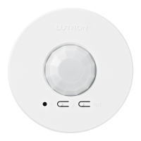
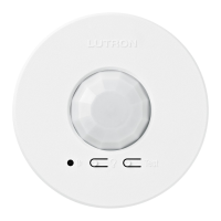
Lists the available sensor model numbers, including color and frequency codes.

Compatible RF Devices

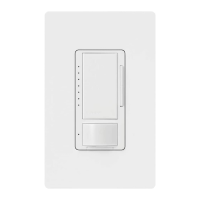
Specifies the Lutron products with which the sensor is compatible.

Specifications and Performance

Regulatory and Standards

Covers certifications, approvals, and quality system registration.

Power and Environment

Details operating voltage, current, battery life, and operating temperature.

Range and Coverage Testing

Defines sensor range and methods for testing coverage and communication.

Operational Settings

Explains timeout, auto-on, and activity settings for sensor operation.

Installation Overview

Sensor Setup and Placement

Guidelines for initial sensor setup and optimal placement for motion detection.

Mounting Options

Drop Ceiling Mounting

Instructions for mounting the sensor in compressed fiber ceiling tiles.

Solid Ceiling Mounting

Methods for permanent and temporary mounting on solid ceilings.

Recess-Mounting

Details on using a recess-mounting ring for flush installation.

Dimensions

Range Diagrams and Coverage Chart

Sensor Coverage Chart

Table detailing maximum square coverage area based on ceiling height.

Lens Masking

Related product manuals