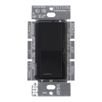
Maestro Sensor
369666f 12 09.05.19
SPECIFICATION SUBMITTAL Page
Job Name:
Job Number:
Model Numbers:
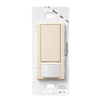
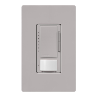
Switch with Occupancy / Vacancy Sensor
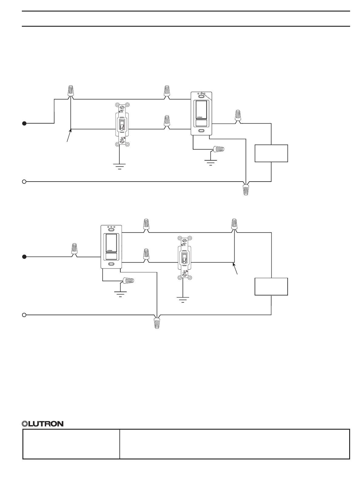
Wiring Diagrams (continued)
1
A single standard mechanical 3-way switch or up to 9 companion switches may be connected to most occupancy sensor switches.
Standard mechanical 3-way switch cannot be combined with companion switch. Total blue terminal wire length may be up to 150ft (46m).
2
Only one occupancy sensor switch can be used per multi-location circuit.
3
Fan load applies to 120 V~ only (not for 277 V~).
4
Occupancy sensor switch can be installed in any location.
Continued on next page...
Wiring Diagram 4 - with Neutral
3-way Installation with Standard Mechanical Switch (277 V~)
1, 2, 3
-OPS6M2-DV, -VPS6M2-DV
Black
Blue
White
Ground
Green
screw
Ground
120 V~
50 / 60 Hz
Hot/Live
Neutral
Load
Standard
mechanical switch
Black
Jumper wire
Bare
Different color
screw (Common)
OR
Black
Blue
Ground
White
Ground
120 V~
50 / 60 Hz
Hot/Live
Neutral
Load
Standard
mechanical switch
Black
Jumper wire
Bare
Different color
screw (Common)
Green
screw
Note: When a neutral connection is available, remove the green sleeve and connect the white wire to neutral.
Occupancy
sensor switch
Occupancy
sensor switch