EasyManua.ls Logo

Lutron Electronics MAESTRO MS-VPS2 - User Manual

Lutron Electronics MAESTRO MS-VPS2
23 pages
To Next Page IconTo Next Page
Loading...
Maestro Sensor
369666f 1 09.05.19
®
SPECIFICATION SUBMITTAL Page
Job Name:
Job Number:
Model Numbers:
Switch with Occupancy / Vacancy Sensor
Maestro sensor switch
The Lutron Maestro occupancy sensor switch combines a
Maestro switch with a passive infrared occupancy or vacancy
sensor. The sensor detects the heat from occupants moving
within an area to determine whether the space is occupied.
Based on the feedback from the sensor, the occupancy sensor
switch will adjust the load accordingly.
Features
Passive infrared sensors with exclusive Lutron XCT Technology
for fine motion detection
180° sensor field-of-view
Up to 30 ft x 30 ft (9 m x 9 m) [900 ft
2
(81 m
2
)] major motion
coverage and 20 ft x 20 ft (6 m x 6 m) [400 ft
2
(36m
2
)] minor
motion coverage
Occupancy version can be set to Auto-ON / Auto-OFF or
Manual-ON / Auto-OFF
Vacancy version available to meet CA Title 24 requirements
Adjustable timeout (1, 5, 15, or 30 minutes) and high/low
sensitivity adjustment
Load types: incandescent, halogen, ELV, MLV, CFL, LED,
magnetic fluorescent, electronic fluorescent, and fan.
Note: "XX" in model number represents color/finish code.
Models available
MS-OPS2-XX
1
MS-OPS2H-XX-C
2
MS-OPS5M-XX
3
MS-OPS5MH-XX-C
2
MS-OPS6M2-DV-XX
MS-OPS6M2U-DV-XX
UMS-OPS6M2-DV-XX
MS-VPS2-XX
1
MS-VPS5M-XX
3
MS-VPS6M2-DV-XX
MS-VPS6M2U-DV-XX
UMS-VPS6M2-DV-XX
MS-OPS2
MS-OPS2H-XX-C
MS-OPS5M
MS-OPS5MH-XX-C
MS-OPS6M2-DV
MS-OPS6M2U-DV
UMS-OPS6M2-DV
MS-VPS2
MS-VPS5M
MS-VPS6M2-DV
MS-VPS6M2U-DV
UMS-VPS6M2-DV
1
For clamshell packaging, add an "H" after the "2". Available in AL, IV, LA, and WH.
2
Clamshell packaged product for Canada. Available in AL, IV, LA, and WH.
3
For clamshell packaging, add an "H" after the "M". Available in AL, IV, LA, and WH.
1

Other manuals for Lutron Electronics MAESTRO MS-VPS2

Question and Answer IconNeed help?

Do you have a question about the Lutron Electronics MAESTRO MS-VPS2 and is the answer not in the manual?

Lutron Electronics MAESTRO MS-VPS2 Specifications

General IconGeneral
StyleMaestro
Load Rating (Incandescent/Halogen)600W
Load Rating (LED/CFL)150W
ColorWhite
Voltage120V
WallplateNot included
Warranty1 Year

Summary

Maestro sensor switch

Features

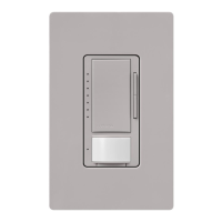
Details passive infrared sensors, field-of-view, coverage, and settings.

Models available

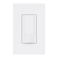
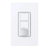
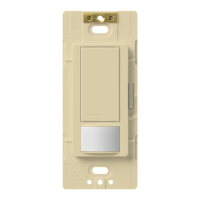
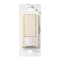
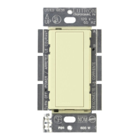
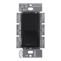
Lists various Maestro sensor switch model numbers.

Specifications

Regulatory Approvals

Lists UL and NOM certifications for the devices.

Power

Specifies voltage and frequency ratings for the sensors.

Key Design Features

Highlights features like lens resistance, ambient light detection, and XCT technology.

Environment

Details ambient temperature and humidity limits for operation.

Warranty

Mentions a 5-year limited warranty and where to find more information.

Additional Information

Provides references for GFI circuits, dimmer models, and multi-location use.

Advanced Features

Switching

Explains standard and adaptive zero cross switching for relay life.

XCT Technology

Describes advanced sensing for fine motion detection and false turn-on prevention.

Custom Settings

Ambient Light Detection

Explains how the sensor adjusts to natural light levels for automatic on/off.

Sensor Operation

Outlines available sensor modes like Auto-ON/Auto-OFF and Manual-ON/Auto-OFF.

Timeout Options

Lists available timeout durations for automatic light shutoff.

Sensitivity Options

Describes the high and low sensitivity settings for motion detection.

Auto-ON Options

Details occupancy and vacancy auto-on configurations and low light features.

Manual Off-While-Occupied Options

Explains options for manually turning off lights while the room is occupied.

Placement and Operation

Definitions

Defines "Major motion" and "Minor motion" for sensor context.

NEMA WD7 Coverage

Details major and minor motion coverage areas and diagrams.

Dimensions

Ganging

Explains how to gang controls in a wallbox and remove fins.

Wiring Diagrams

Wiring Diagram 1: Single Location (120 V~) with Neutral

Illustrates single location wiring for -OPS2 and -VPS2 with neutral.

Wiring Diagram 1: Single Location (120 V~) without Neutral

Illustrates single location wiring for -OPS2 and -VPS2 without neutral.

Wiring Diagram 2: Single Location (120 V~) with Neutral

Shows wiring for -OPS5M, -OPS6M2-DV, -VPS5M, -VPS6M2-DV with neutral.

Wiring Diagram 2: Single Location (120 V~) without Neutral

Shows wiring for -OPS5M, -OPS6M2-DV, -VPS5M, -VPS6M2-DV without neutral.

Wiring Diagrams (continued)

Wiring Diagram 3: 3-Way Installation (120 V~) with Neutral

Details 3-way wiring for specific models with neutral.

Wiring Diagrams (continued)

Wiring Diagram 3: 3-Way Installation (120 V~) without Neutral

Details 3-way wiring for specific models without neutral.

Wiring Diagrams (continued)

Wiring Diagram 4: 3-Way Installation (277 V~) with Neutral

Shows 3-way wiring for specific models at 277V with neutral.

Wiring Diagrams (continued)

Wiring Diagram 4: 3-Way Installation (277 V~) without Neutral

Shows 3-way wiring for specific models at 277V without neutral.

Wiring Diagrams (continued)

Wiring Diagram 5: Multi-Location (120 V~) with Neutral

Details multi-location wiring with companion switches (120V) with neutral.

Wiring Diagram 5: Multi-Location (120 V~) without Neutral

Details multi-location wiring with companion switches (120V) without neutral.

Wiring Diagrams (continued)

Wiring Diagram 6: Multi-Location (277 V~) with Neutral

Details multi-location wiring with companion switches (277V) with neutral.

Wiring Diagram 6: Multi-Location (277 V~) without Neutral

Details multi-location wiring with companion switches (277V) without neutral.

Wiring Diagrams (continued)

Wiring Diagram 7: Single Location (120-277 V~) with Neutral

Shows single location wiring for specific models (120-277V) with neutral.

Wiring Diagram 7: Single Location (120-277 V~) without Neutral

Shows single location wiring for specific models (120-277V) without neutral.

Wiring Diagrams (continued)

Wiring Diagram 8: 3-Way Installation (120 V~) with Neutral

Details 3-way wiring for specific models (120V) with neutral.

Wiring Diagrams (continued)

Wiring Diagram 8: 3-Way Installation (120 V~) without Neutral

Details 3-way wiring for specific models (120V) without neutral.

Wiring Diagrams (continued)

Wiring Diagram 9: 3-Way Installation (277 V~) with Neutral

Details 3-way wiring for specific models (277V) with neutral.

Wiring Diagrams (continued)

Wiring Diagram 9: 3-Way Installation (277 V~) without Neutral

Details 3-way wiring for specific models (277V) without neutral.

Wiring Diagrams (continued)

Wiring Diagram 10: Multi-Location (120 V~) with Neutral

Shows multi-location wiring with companion switches (120V) with neutral.

Wiring Diagram 10: Multi-Location (120 V~) without Neutral

Shows multi-location wiring with companion switches (120V) without neutral.

Wiring Diagrams (continued)

Wiring Diagram 11: Multi-Location (277 V~) with Neutral

Details multi-location wiring with companion switches (277V) with neutral.

Wiring Diagram 11: Multi-Location (277 V~) without Neutral

Details multi-location wiring with companion switches (277V) without neutral.

Colors and Finishes

Gloss Finishes

Displays available colors in a gloss finish.

Satin Finishes

Displays available colors in a satin finish.

Related product manuals