31
P/N 032498h
Continued on next page...
Appendix A
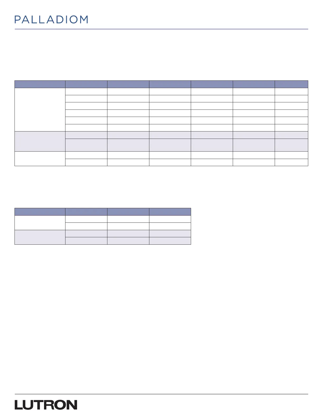
1. Heat Stage Relays
This table indicates the relays that will be energized for each heat stage based on the system type.
Table 17:
System Heat Stages Auxiliary Heat 1st Heat Stage 2nd Heat Stage 3rd Heat Stage Auxiliary Only
Heat Pump
1
1 None Y
1
and G
2 None Y
1
and G Y
1
, Y
2
, and G
2 Electric Y
1
and G Y
1
, W
2
, and G W
2
and G
2 Gas / Oil Y
1
and G W
2
and G W
2
and G
3 Electric Y
1
and G Y
1
, Y
2
, and G Y
1
, Y
2
, W
2
, and G W
2
and G
3 Gas / Oil Y
1
and G Y
1
, Y
2
, and G W
2
and G W
2
and G
Conventional, thermostat
controlled heating fan
1 None W
1
and G
2 None W
1
and G W
1
, W
2
, and G
Conventional, equipment
controlled heating fan
1 None W
1
2 None W
1
W
1
and W
2
2. Cool Stage Relays
This table indicates the relays that will be energized for each cool stage based on the system type.
Table 18:
System Heat Stages Auxiliary Heat 1st Heat Stage
Heat Pump
1
1 Y
1
, G, and O
2 Y
1
, G, and O Y
1
, Y
2
, G, and O
Conventional
1 Y
1
and G
2 Y
1
and G Y
1
, Y
2
, and G
1
Included with SMC55-HWQS version 7420 or newer, SMC55-RESI version 7302 or newer and HomeWorks Palladiom Thermostat version 1.10 or newer.