EasyManua.ls Logo

Lux Products SMART TEMP TX9100Uc User Manual

Lux Products SMART TEMP TX9100Uc
36 pages
To Next Page IconTo Next Page
Page #1 background imageLoading...
Page #1 background image
CAUTIONS AND WARNINGS . . . . . . . . . . 2
SYSTEM COMPATIBILITY . . . . . . . . . . . . 3
FEATURES . . . . . . . . . . . . . . . . . . . . . . . 4
TOOLS YOU MAY NEED . . . . . . . . . . . . . . 4
MOUNTING LOCATION . . . . . . . . . . . . . . 5
REMOVE OLD THERMOSTAT . . . . . . . . . . 5
INSTALL THERMOSTAT BASE . . . . . . . . . 6
WIRING INFORMATION . . . . . . . . . . . . . . 7
WIRING DIAGRAMS . . . . . . . . . . . . . . . . 9
COMPLETE THE INSTALL . . . . . . . . . . . 18
FRONT PANEL ITEMS . . . . . . . . . . . . . . 18
SYSTEM CONFIGURATION AND
SETUP OPTIONS. . . . . . . . . . . . . . . . . . 19
OPERATING INSTRUCTIONS . . . . . . . . . 23
TEMPERATURE PROGRAMS . . . . . . . . . 25
ADVANCED FEATURES . . . . . . . . . . . . . 26
BATTERY REPLACEMENT . . . . . . . . . . . 34
TECHNICAL ASSISTANCE . . . . . . . . . . . 35
LIMITED WARRANTY . . . . . . . . . . . . . . 35
MERCURY NOTICE . . . . . . . . . . . . . . . . 36
WARNING: Use Energizer
®
or DURACELL
®
Alkaline Batteries Only.
Energizer
®
is a registered trademark of Eveready Battery Company, Inc.
DURACELL
®
is a registered trademark of The Procter & Gamble Company
© 2014 LUX PRODUCTS CORPORATION. ALL RIGHTS RESERVED
T X 9 1 0 0 U c
SMART TEMP
®
UNIVERSAL
7-DAY PROGRAMMABLE THERMOSTAT
(FOR BOTH CONVENTIONAL AND HEAT PUMP SYSTEMS)
I N S TA L L AT I O N A N D O P E R AT I N G I N S T R U C T I O N S
IMPORTANT!
Please read all of these instructions carefully before beginning
installation.
Label every wire terminal designation on your existing thermostat wiring
before removing your old thermostat.
Ignore the color of the wires since they may not comply with any
standard. Please connect wires using the terminal letter designations.
Thank you for your confidence in our product. To obtain the best results from
your investment, please read and follow the installation procedures carefully, and
one step at a time. This will save you time and minimize the chance of damaging
either the thermostat or possibly your heating and cooling system. These
instructions may contain information beyond that which may be required for your
particular installation.
52174
Question and Answer IconNeed help?

Do you have a question about the Lux Products SMART TEMP TX9100Uc and is the answer not in the manual?

Lux Products SMART TEMP TX9100Uc Specifications

General IconGeneral
Wi-Fi ConnectivityYes
Programmability7-day programmable
Filter Change AlertYes
CompatibilityMost HVAC systems
DisplayBacklit
Mobile AppLux App
Voice ControlAmazon Alexa, Google Assistant
Power Source24VAC (C-wire required)
FeaturesGeofencing
Hold FeatureYes
InstallationDIY installation
TypeSmart Thermostat
Temperature Range40°F to 90°F (4°C to 32°C)
Backup BatteryYes, 2 AA batteries

Summary

Safety and Warnings

System Compatibility

Thermostat Features

Installation Tools Required

Mounting Location Guidelines

Removing the Old Thermostat

Installing the Thermostat Base

Wiring Information and Notices

Connecting the Wires

Ensures proper connection of wires to the terminal block for thermostat operation.

Wiring Base Plate Notice

Caution against interchanging base plates or front halves of similar models.

Wiring Diagrams Overview

Diagram #1: Conventional Heating Only

Wiring for 1-stage or 2-stage conventional heating systems, including millivolt.

Diagram #2: Hot Water Heating Only

Wiring for hot water heating with a 3-wire zone valve.

Diagram #3: Conventional Cooling Only

Wiring for 1-stage or 2-stage conventional cooling systems.

Diagram #4: Conventional Heating and Cooling

Wiring for 1-stage conventional heating and 1-stage cooling.

Diagram #5: Conventional Heating and Cooling

Wiring for 2-stage conventional heating and 2-stage cooling.

Diagram #6: Conventional Heating and Cooling (Two Transformers)

Wiring for conventional systems with two separate 24V transformers.

Diagram #7: Single-Stage Heat Pump

Wiring for single-stage heat pump systems with no auxiliary or emergency heat.

Diagram #8: Heat Pump with Aux/Emergency Heat

Wiring for 2-heat/1-cool heat pump systems with auxiliary and emergency heat.

Completing the Installation

Front Panel Controls

System Configuration and Setup

Understanding Buttons

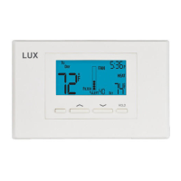
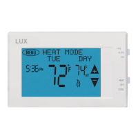
Description of UP/DOWN, HOLD, COPY/EMER, and NEXT button functions.

Accessing the Setup Menu

Procedure to enter the thermostat's setup menu for configuration.

Setup Item #01: Clock Format

Setting the clock display format between 12-hour and 24-hour.

Setup Item #02: Temperature Scale

Selecting the temperature display unit between Fahrenheit and Celsius.

Setup Item #03: Thermostat Type

Configuring the thermostat for programmable or manual operation.

Setup Item #04: Period Quantity

Choosing between 4 or 2 daily program periods (MORN, DAY, EVE, NITE).

Setup Item #05: Early Recovery

Enabling or disabling the early recovery feature for temperature transitions.

Setup Item #06: System Mode

Selecting the system type: Furnace (FURN) or Heat Pump (HP).

Setup Item #07: Fan 'G' Terminal Operation

Configuring fan control behavior in HEAT/EMERG HEAT modes.

Setup Item #08: Delay Time

Setting the internal delay time (2 or 5 minutes) for system cycling.

Setup Item #09: Temperature Swing

Adjusting the temperature variation (swing) for system cycling frequency.

Setup Item #10: Stage-2 Offset

Setting an offset for the second heating stage to conserve energy.

Operating Instructions

Setting Day and Time

Procedure for setting the current day and time on the thermostat.

Heating and Cooling Modes

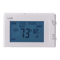
Basic operation for controlling heating and cooling systems.

Emergency Heat Mode

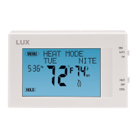
Activating and using emergency heat for heat pump systems.

LCD Display Backlight

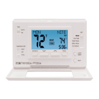
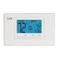
Information on how the display backlight functions and activates.

Temperature Override

Temporarily changing the set temperature without altering the program.

Temperature Hold

Maintaining a fixed set temperature indefinitely.

Temperature Programming

Setting Temperature Programs

Steps to program daily temperature schedules for heating and cooling.

Program Copy Feature

Copying program settings from one day to another.

Advanced Features

Temperature Calibration

Adjusting the thermostat's temperature sensor reading.

Setback Feature

Setting temporary temperature adjustments for specific durations.

Special Program Feature

Creating temporary, custom programs for specific periods (e.g., vacations).

Temperature Limit Stops

Setting maximum heat and minimum cool temperature limits.

Setting Heat Limit Stop

Procedure to set the maximum allowable heat temperature.

Setting Cool Limit Stop

Procedure to set the minimum allowable cool temperature.

Changing Temperature Stop Lock Code

Setting or resetting the 2-digit code for temperature limit access.

Keypad Lockout

Locking the thermostat's front panel buttons for security.

Air Filter Monitor

Setting Air Filter Duration

Configuring the filter replacement reminder interval.

Resetting Filter Usage Counter

Resetting the air filter usage timer.

Energy Usage Monitor

Viewing Heat Usage Timers

Displaying today's, yesterday's, and total heat system runtime.

Viewing Cool Usage Timers

Displaying today's, yesterday's, and total cooling system runtime.

Hardware Reset Procedure

Software Reset

Compressor Protection Bypass

Battery Replacement

Battery Graphic Indicator

Understanding the display's battery life indicator and low battery warning.

Technical Assistance

Limited Warranty Information

Mercury Warning and Recycling

Related product manuals