D. Move the connecting rod to the "Install" position on the Connecting Rod Bushing
Replacement Block or equivalent and clamp it securely in place.
E. Use the Replacement Drift P/N 64536 or equivalent to install the new connecting rod bushing
in the connecting rod.
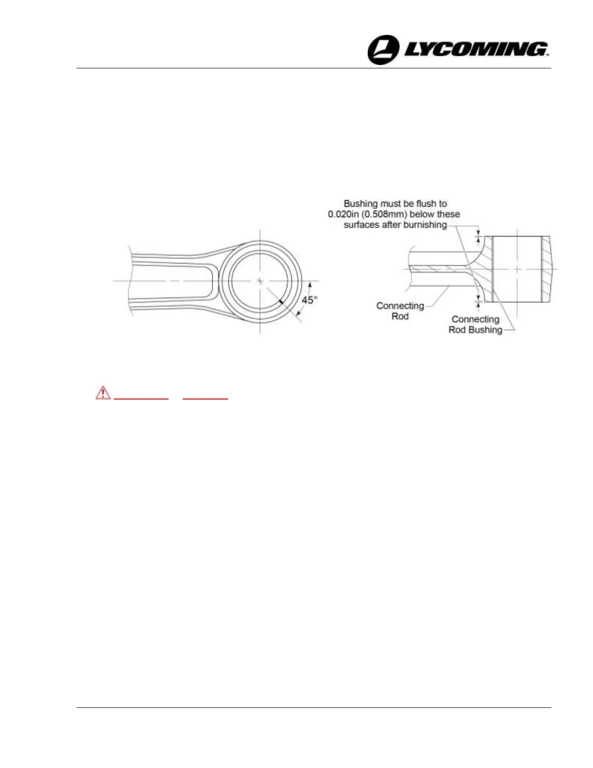
F. Make sure the split in the bushing is located so that it is toward the piston end of the
connecting rod and 45° off the centerline (Figure 27) and press the bushing into the
connecting rod until the edge of the bushing is flush with the surface of the connecting rod.
CAUTION DO NOT BURNISH CONNECTING ROD BUSHING P/N 01K28983.
THESE BUSHINGS ARE NOT DESIGNED TO BE BURNISHED AFTER
INSTALLATION. BURNISHING MAY RESULT IN DAMAGE TO
BUSHING P/N 01K28983.
G. Examine the bushing after installation to make sure the bushing is flush to 0.020 in. (0.508
mm) below the connecting rod surface (Figure 28) on both sides of the connecting rod.
H. Remove the connecting rod from the holding block and complete a final bore of the bushing
to the diameter shown in the latest revision of the Service Table of Limits - SSP-1776.
If using a carbide cutter when final boring the 01K28983 bushing, Lycoming recommends an
approximate spindle speed of 730 RPM and a feed rate of .003 in. per revolution.
I. As a check, measure the bushing inner diameter with the Finish ID Gage P/N 64767 or
equivalent.
J. Complete the “Connecting Rod Parallelism/Squareness Check” in this chapter.
K. If the assembly does not pass this check, replace the connecting rod assembly.
L. Record all maintenance completed, include the P/N of the new bushing, in the engine
logbook.



 To Next Page