Instructions for Magneto Inspection, Magneto-to-Engine Timing Check, Magneto-to-Engine Timing
Adjustment Procedure, Magneto Replacement Procedure, are as follows:
1. Magneto Inspection
Examine the magneto in accordance with the magneto manufacturer's instructions after every 500
hours of engine operation.
2. Magneto-to-Engine Timing Check
A. Disconnect the ignition leads from all spark plugs.
B. Remove the nut and lock washer from the condenser terminal on the magneto. Disconnect the
P-Leads from the magneto. Discard the lock washer.
C. Remove one of the spark plugs from Cylinder No. 1 per the “Spark Plug Removal” procedure
in Chapter 74-20.
D. Turn the crankshaft in the direction of normal rotation until Cylinder No. 1 is on the
compression stroke, approximately 35° before TDC.
E. Put your thumb over the spark plug hole and turn the crankshaft in the direction of normal
rotation until there is pushback pressure at the spark plug hole.
NOTICE: Some timing lights operate in the reverse manner than identified herein. The light
comes on when the contact points open. Refer to your timing light instructions.
F. Connect the timing light leads to the appropriate magneto condenser terminals and the
ground lead to any unpainted portion of the engine.
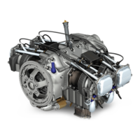
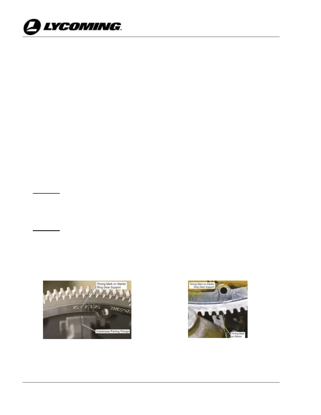
NOTICE: There are two reference points on the engine to be used when aligning the timing
marks on the starter ring gear support:
• When viewing the starter ring gear support assembly from the crankcase side,
the reference point is the crankcase parting flange (Figure 1).
• When viewing the starter ring gear support assembly from the propeller side,
the reference point is the timing mark on the starter (Figure 2).