E. Install the new lubricated matched set bearing pair on each connecting rod, one bearing on
the connecting rod and the other bearing on the connecting rod cap. Ensure that the tang of
each bearing fits and seats within the slot of the connecting rod as well as the connecting rod
cap.
NOTICE: Do not install standardized connecting rod bolts in connecting rods with oversize
bolt holes. Refer to the latest revision of Service Instruction No. SI-1458 for details.
F. Apply Loctite
®
Food-Grade Anti-Seize Lubricant to the bottom two or three threads of the
new connecting rod bolts (Figure 32). Wipe away excess lubricant with a clean, lint-free
cloth.
G. Install each connecting rod pair (with the bearing inserts installed) on their respective crank
pins on the crankshaft (where the numbers on the connecting rods and caps point down -
toward the oil sump.)
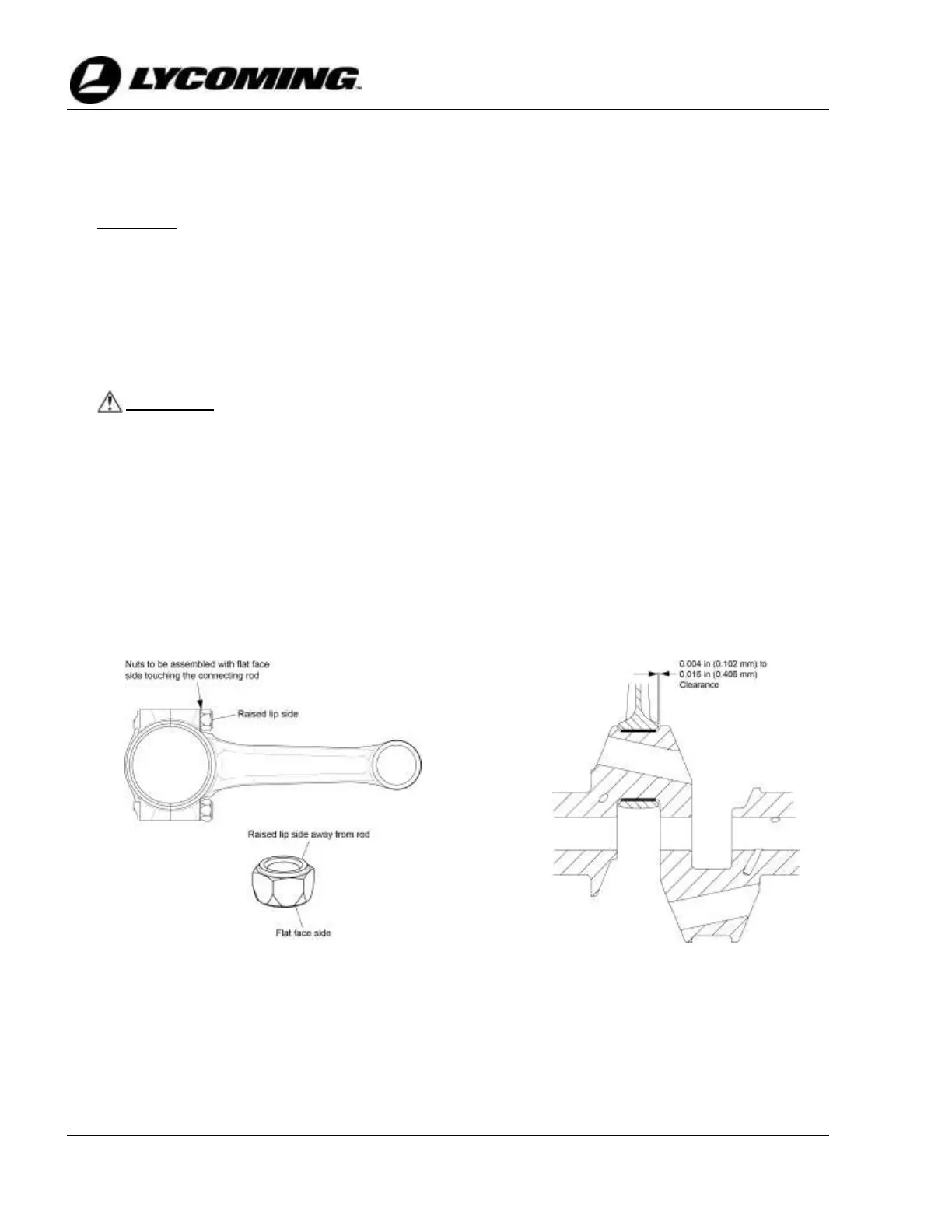
CAUTION: CORRECT INSTALLATION OF THE NEW NUT ON EACH NEW
CONNECTING ROD BOLT IS NECESSARY FOR CORRECT
CONNECTING ROD ASSEMBLY. EACH CONNECTING ROD NUT
HAS TWO DIFFERENT SURFACES, ONE SURFACE IS FLAT AND
THE OTHER HAS A RAISED LIP. BE SURE TO INSTALL EACH NUT
ON THE CONNECTING ROD BOLT WITH THE FLAT FACE
TOUCHING THE ROD. THE RAISED LIP SURFACE IS AWAY FROM
THE ROD. THE CONNECTING ROD BOLT CANNOT BE TIGHTENED
CORRECTLY IF THE NUT ON THE CONNECTING ROD IS
INSTALLED INCORRECTLY.
H. Install a new nut on each new connecting rod bolt where the flat face of the nut touches the
connecting rod as shown in Figure 33.
I. Torque the connecting rod bolts per the torque values in the latest revision of Service
Instruction No. SI-1458. (Stretch bolts require an initial torque and are then torqued to the
correct stretched length.)
J. Measure the side clearance between the connecting rod and crankshaft with a feeler gage
where shown in Figure 34. The clearance is to be 0.004 to 0.016 in (0.102 to 0.406 mm).



 To Next Page