Do you have a question about the Lynx Napoleon Lynx LDT and is the answer not in the manual?
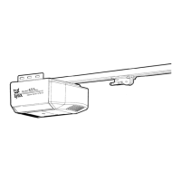
Details of the operator's motor specifications including type, HP, speed, and voltage.
Electrical specifications covering transformer, control station, wiring type, and limit adjustment.
Mechanical details including drive reduction, output shaft speed, door speed, brake, and bearings.
Safety features and recommendations, including disconnect, photo eyes, and reversing edge.
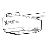
Information on the operator's hanging weight and overall dimensions.
Instructions for assembling the operator rail, including idlers and mounting points.
Steps for attaching the operator assembly to the door frame using bolts and nuts.
Procedure for routing and tensioning the drive chain using master links and the chain tensioner.
Guide for mounting the wall bracket, including marking lines and ensuring header suitability.
Steps to mount the operator onto the wall mount, securing it with pivot bolts and supporting the rail.
Instructions for hanging the operator from the ceiling using support braces for strength.
Steps to attach the curved arm to the door bracket and connect it to the trolley's straight arm.
Procedures for disconnecting and reconnecting the door from the operator for manual operation.
Information on compatible sensing edges, their mounting, and wiring requirements.
Guide on adjusting limit nuts to set the door's open and close positions correctly.
Detailed instructions for making electrical power connections, emphasizing consulting the wiring diagram.
Explanation of wiring modes (C2, B2) and their requirements, including entrapment protection devices.
Guidelines for mounting the control station for safe and accessible operation.
Information on internal antennas, optional radio transmitters, and wiring for receivers.
Details on connecting external access controls and safety devices to the operator board.
How to wire an external interlock switch to control door operation.
Step-by-step guide for mounting and wiring photo eyes for safety and proper door operation.
Explains the three operating modes: B2, C2, and TS, and their default settings.
Details the C2 mode operation, requiring constant pressure for closing.
Details the B2 mode operation, allowing momentary contact for opening or closing.
Details the TS mode operation, including Timer to Close (TTC) functionality.
Instructions for programming remote transmitters to the operator's LX900 controller.
Procedure for erasing all previously programmed remote transmitters from the operator.
Steps for adjusting the clutch tension to ensure smooth door movement and safety slip.
Guide for adjusting the brake pads for proper engagement and disengagement.
Instructions for testing controls and safety devices after installation or maintenance.
Schedule for routine maintenance checks on components like drive chain, clutch, and brake.
Shows the internal factory wiring connections for the operator's components.
Illustrates external wiring connections for control stations, photo eyes, and safety devices.
Provides dimensional information and layout for the operator installation.
| Brand | Lynx |
|---|---|
| Model | Napoleon Lynx LDT |
| Category | Garage Door Opener |
| Language | English |