11
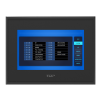
Rear Part Names and Specifications
Shock Absorber for Panel Mounting
Contrast Adjust
In this model, Contrast Adjust is possible in [Setup]
in Menu mode
XTOP04: 9 pin, XTOP07: 15 pin
For Download/Upload, Serial or USB comm.
In USB, it needs USB to Serial converter[Optional]
Input Voltage 24VDC Typical
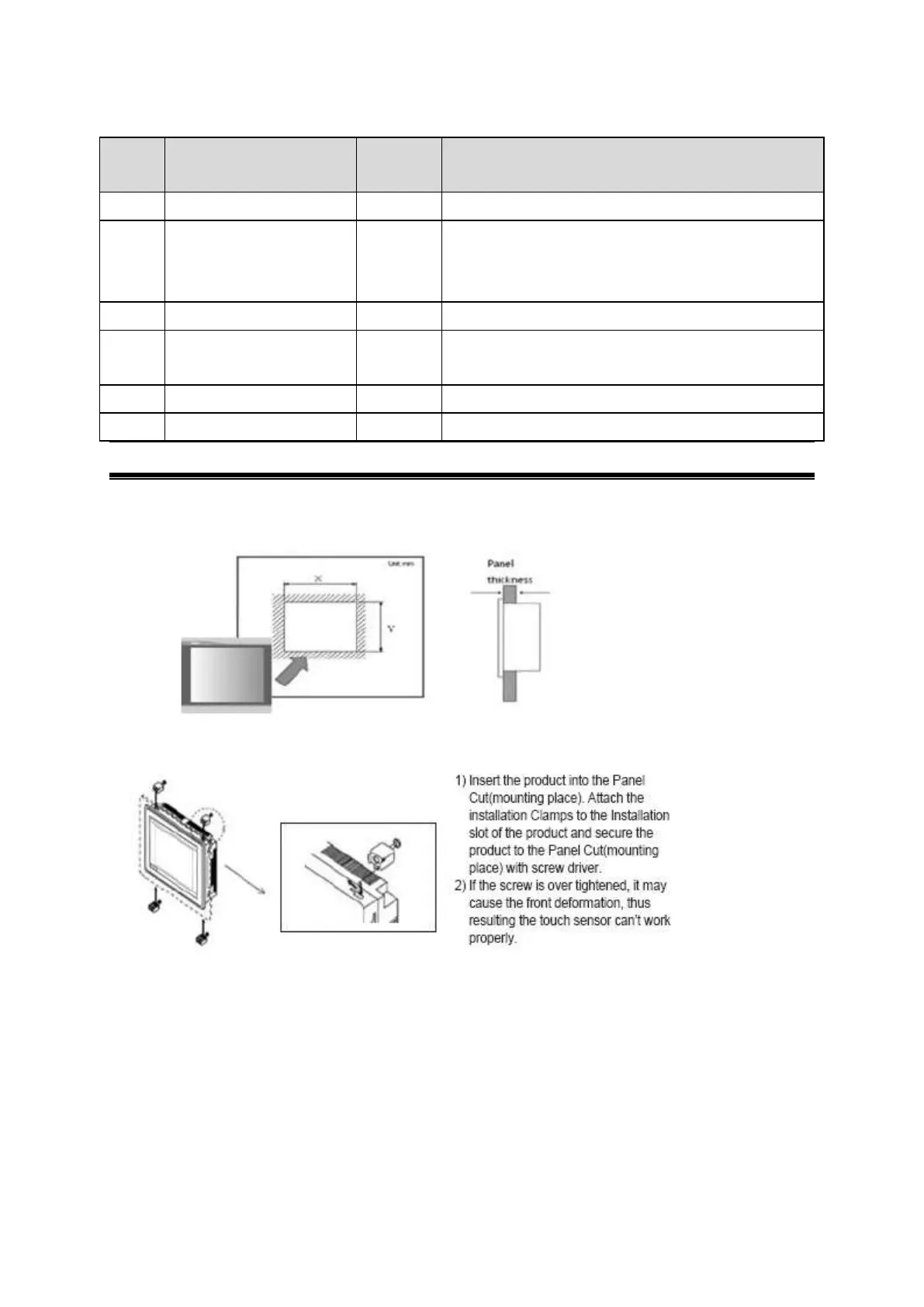
Installation and Panel Cut Size
For mounting product to the control panel, It should be recommended following below items.
Make a panel cut which product is mounted and insert product to the panel form the front side.
Installation methods should be following by using the supplied installation Clamp 4PCS.