EasyManua.ls Logo

M2I TOPRW - User Manual

M2I TOPRW
23 pages
Print Icon
To Next Page IconTo Next Page
Loading...
M2I Corporation Industrial HMI Touch Panel HW Installation Manual
M2I Corporation
M2I Bldg, 35-11, Jeonpa-ro 24beon-gil, Manan-gu, Anyang-si, Gyeonggi-do, 430-857, Korea. Tel :+82-70-465-3366,Fax:+82-31-465-3355 www.m2i.co.kr
1 / 23
M2I Corporation
Industrial HMI Touch Panel
TOPRW
HW Installation Manual
Thank you for purchasing the industrial HMI touch panel series of M2I corporation.
Please read this manual carefully to know installing, wiring, operating this equipment for safe use of
this product.
Chapter1. Safety Precautions
Chapter2. Overview
Chapter3. General Specifications
Chapter4. Part Names and General Specifications
Chapter5. Interface
Chapter6. Installation
Chapter7. Wiring
Chapter8. Maintenance
Chapter9. Warning Label
Chapter10. Products Label
Question and Answer IconNeed help?

Do you have a question about the M2I TOPRW and is the answer not in the manual?

Summary

Chapter 1. Safety Precautions

Before Using the Product

General instructions and warnings for safe and effective product usage, emphasizing reading the manual.

General Precautions

Guidelines for handling, environment, and avoiding damage or electric shock during operation.

Design Precautions

Recommendations for protective circuit installation and wiring separation for system stability.

Wiring Precautions

Guidelines for correct wiring, terminal tightening, and grounding to prevent fire or damage.

Installation Precautions

Advice on avoiding extreme temperatures, shock, vibration, and ensuring proper ventilation.

Disposal Precautions

Instructions for treating product and battery as industrial waste to prevent hazards.

Cell Type Battery Specifications and Exchange

Details on the device's battery voltage, model, lifetime, and replacement procedure.

Chapter 2. Overview

2.1 Introduction of Products

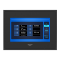
Overview of the industrial HMI touch panel and its role in industrial control and communication.

2.2 Package Contents

List of components included with the product, including the main unit, clamps, and accessories.

2.3 Explanation of Model Name

Decoding the model name structure to understand series, display size, option, resolution, and power.

Chapter 3. General Specifications

3.1 Power Specifications

Details on input voltage, consumption power, voltage endurance, and insulation resistance.

3.2 Memory Specifications

Information on screen memory, backup memory, backup period, and real-time clock.

3.3 Environment Specifications

Operating conditions including temperature, humidity, atmosphere, vibration, and noise immunity.

3.4 Structure Specifications

Specifications related to weight, cooling system, and case material for different models.

Chapter 4. Part Names and General Specifications

4.1 TOPRW0500 WD

Details on the TOPRW0500WD model, including external dimensions and front/rear part identification.

4.2 TOPRW0700 WD

Details on the TOPRW0700WD model, including external dimensions and front/rear part identification.

4.3 TOPRW1000 WD

Details on the TOPRW1000WD model, including external dimensions and front/rear part identification.

Chapter 5. External Device Interface

5.1 Serial Communication Specifications

Technical details for RS-232C and RS-422/485 serial communication, including pinouts.

5.2 Ethernet Communication Specifications

Specifications for Ethernet communication, including speed, method, and RJ-45 pin layout.

5.3 USB Communication Specifications

Details on USB Host and USB OTG communication, including interface and transfer speeds.

Chapter 6. Installation

6.1 Installation Requirements

Key requirements for optimal performance, ventilation, operating environment, and viewing angle.

6.2 Installation Procedure

Step-by-step guide for installing the product, focusing on panel cut-out and fixing methods.

Chapter 7. Wiring

7.1 Power Wiring

Specifications for power cable, F.G cable, conductor type, and bolt tightening force for safe wiring.

7.2 Ground Wiring

Guidelines for exclusive, common, and diverged grounding methods, including cable requirements.

Chapter 8. Maintenance

8.1 Cleaning the Display

Instructions for safely cleaning the device's screen and frame using appropriate cleaning solutions.

8.2 Periodic Check Points

Regular checks for environment, power, and related items to ensure optimal device condition.

8.3 Problems with the Device

Procedure for handling device malfunctions, including contacting support and authorized repairs.

8.4 Setting System Recovery Mode

Steps to set the system recovery mode for factory default state and reboot procedures.

Chapter 9. Products and Warning Label Location

1. TOPRW0500 WD

Location of product and warning labels on the TOPRW0500WD model.

2. TOPRW0700 WD; TOPRW1000 WD

Location of product and warning labels on the TOPRW0700WD and TOPRW1000WD models.

Chapter 10. Products Label

Overview

The M2I Corporation Industrial HMI Touch Panel, branded as TOPRW, is an industrial control device designed for communication with other devices like PLCs. This manual provides comprehensive information for its safe installation, wiring, operation, and maintenance.

Function Description

The TOPRW series serves as an industrial Human-Machine Interface (HMI) touch panel. It facilitates communication with external devices primarily through RS-232C, RS-422/485, and Ethernet interfaces. Its core function is to provide a visual and interactive platform for controlling and monitoring industrial processes. The device supports various communication protocols and data types, making it versatile for integration into diverse industrial automation systems.

Important Technical Specifications

Power Specifications:

  • Input Voltage: DC 24V
  • Input Voltage Range: DC 20~28V
  • Consumption Power:
    • TOPRW0500WD: Under 12W
    • TOPRW0700WD: Under 12W
    • TOPRW1000WD: Under 15W
  • Voltage Endurance: DC 24V, Within 10 ms
  • Insulation Resistance: 500V DC, 10 MΩ

Memory Specifications:

  • Screen Memory: 128MB
  • Backup Memory: 512KB (System buffer: 5K Word, including Alarm/Logging/Recipe)
  • Backup Period: Permanent
  • Real Time Clock: Built-in (by Battery)

Environment Specifications:

  • Operation Temperature: -10 ~ +50 °C
  • Storage Temperature: -20 ~ +60 °C
  • Operation Humidity: 0 ~ 90% RH (No dew)
  • Atmosphere: No corrosive gas
  • Vibration Endurance: Amplitude: 10 ≤ F < 25 Hz (2G) X,Y,Z each direction (for 30 minutes)
  • Noise Immunity: 1000Vp-p (Pulse width 1 µs)
  • Static Electricity Discharge: Connective discharge from EN61000-4-2: ±4 kV
  • Shock Endurance: 10G X,Y,Z each direction (for 3 times)
  • Surge Voltage: 500V (Line-Line)
  • Ground Connection: Class 3 (Under 100Ω)
  • Protection Classification: Conform to IP65

Structure Specifications:

  • Weight:
    • TOPRW05: 0.4 kg
    • TOPRW07: 0.72 kg
    • TOPRW10: 1.7 kg
  • Cooling System: Natural Air Circulation
  • Case Material: PC (Flameless)

Display Sizes and Resolutions (Model Name Explanation): The model name TOPRW includes information about display size, option, resolution, and power type.

  • Display Size: 05 (5.0"), 07 (7.0"), 10 (10.2")
  • Option: 00 (Standard), 10 (Premium)
  • Resolution: Q (QVGA 320x240), V (VGA 640x480), S (SVGA 800x600), X (XGA 1024x768), W (WQVGA 480x272), WVGA (800x480)
  • Power: A (AC), D (DC)

Serial Communication (RS-232C & RS-422/485):

  • Protocol: Half Duplex
  • Synch: Asynchronous
  • Communication Distance:
    • RS-232C: About 15m
    • RS-422/485: About 500m
  • Type of Connection:
    • RS-232C: 1:1
    • RS-422/485: 1:N (N ≤ 31)
  • Control Code: ASCII Code or HEXA Code
  • Transmission Speed: 2400, 4800, 9600, 19200, 38400, 57600, 76800, 115200 bps
  • Data Bit: 7, 8 bit
  • Parity Bit: NONE, ODD, EVEN Parity
  • Stop Bit: 1, 2 bit
  • Modular Jack: DSUB 9pin
  • COM1 Connector: RS-232C Serial Comm. (DSUB9)
  • COM2 Connector: RS-232C/422/485 Serial Comm. (DSUB9, switchable via software)
    • COM1 Pin 7 (VCC1) and Pin 8 (VCC GND1) provide +5V, 0.2A for external equipment.

Ethernet Communication:

  • Ethernet Method: IEEE802.3i/IEEE802.3u, 10BaseT / 100BaseT
  • Speed: 10M / 100Mbps
  • Communication Method: Base Band
  • Switching Method: AUTO MDIX
  • Maximum Segment Length: 100m (Hub between product)
  • Communication Cable: UTP (Unshielded Twisted Pair)
  • Modular Jack: RJ45 (1 channel)

USB Communication:

  • USB Host (Type A, 1 channel):
    • Interface: EHCI/OHCI Specification Version 1.0, USB2.0/1.1 compatible
    • Communication Method: Control/Bulk
    • Transfer Speed: 480Mb/s
    • Support Device: USB Storage (FAT16/FAT32 File Format Available)
  • USB OTG (MINI USB AB, Female):
    • Interface: USB 2.0
    • Communication Method: Interrupt/Bulk/Isochronous
    • Transfer Speed: 480Mb/s
    • Supporting OS: Windows 98SE/2000/XP/VISTA/7/10 (32/64bit)
    • Cable Length: 1.5M (recommended to use M2I's Option Cable)
    • Connect Method: TOPRW05 (via USB terminal inside SD cover), TOPRW07/10 (via USB Front of Display Module)

Cell Type Battery:

  • Model: MS920SE (lithium / Rechargeable)
  • Voltage: DC 3V
  • Lifetime: Permanent (at 25°C ambient temperature)
  • Discharge: Lasts about 7 days after power off.
  • Note: Not user-replaceable; contact Customer Support Center for replacement.

Usage Features

Installation:

  • Safety Precautions: Emphasizes reading the manual thoroughly to prevent accidents. Warnings highlight potential for serious personal injury or death, while Cautions indicate slight personal injury or product damage.
  • Environmental Requirements: Must be installed within 0°C to 50°C ambient temperature and 10-80% relative humidity (no dew). Avoid high vibration, direct sunlight, and corrosive gas environments.
  • Space Requirements: Maintain at least 100mm clearance between the back of the main unit and container walls for ventilation and maintenance. A cooling fan is recommended for enclosed spaces.
  • Panel Cut-out: Specific dimensions are provided for each model (TOPRW0500WD, TOPRW0700WD, TOPRW1000WD) to ensure proper mounting.
  • Fixing: Clamps are used to secure the unit into the panel cut. Screws should be tightened to a torque of 0.2 N.m to prevent front deformation and touch sensor malfunction.
  • Slanted Installation: If installed at an angle, the screen should not incline more than 30°.

Wiring:

  • Power Wiring: Use 0.75~2.5mm² (18~12AWG) power cable and over 4mm² (11AWG) for FG cable. Bolt tightening force should be ≥ 0.2 N.m. Field-installed conductors must have a temperature rating of 65°C Only. All field-wiring connections must be from a Limited Voltage / Limited Current, below 24 Vdc isolated secondary source with an output fuse, or Class 2.
  • Ground Wiring: The product has anti-noise measures, but grounding is recommended in noisy environments. Use Class 3 grounding (ground resistor < 100Ω) and an exclusive ground if possible. If not, common grounding is acceptable. The ground cable should be more than 4mm² and as short as possible, close to the product.
  • Communication Wiring: For RS-232C, cross RD and SD lines with a Twisted Pair Cable and connect SG directly. For RS-422/485, use Twisted Pair Cable for RDA/RDB and SDA/SDB. Do not use shield wire as signal ground.
  • Ethernet Wiring: Use Straight cable when connecting to a HUB. If connecting directly without a HUB, use Cross Cable (TD+ and RD+ exchanged, TD- and RD- exchanged).

Package Contents: The product package includes the process module, manual, clamps (4 units), and a power connector. Optional accessories (sold separately) include a USB memory, USB cable, SD card, and front protect sheet.

Maintenance Features

Cleaning the Display:

  • Spray cleaning solution onto a soft cloth and wipe the display surface or frame. Do not spray directly onto the device.

Periodic Check Points:

  • Environment: Verify that operating temperature (-10°C~50°C), humidity (10%~80%RH), and absence of corrosive gas are maintained.
  • Power: Check if the input voltage is within the specified range (-15%~+10%).
  • Related Items: Inspect the LCD Backlight for its guarantee duration and the touch pad for any damage, scratches, or pollution.

Problems with the Device:

  • If operational problems occur, stop use immediately and contact M2I Corporation's A/S department.
  • Only authorized M2I personnel can inspect and repair malfunctions.
  • If on-site resolution is not possible, the equipment may be sent to M2I Corporation.
  • M2I Corporation is not responsible for damage or malfunction caused by user conditions outside the manual's installation and use standards.

System Recovery Mode:

  • Function: A built-in recovery function allows restoring the device to factory default settings if the system fails to boot normally. Note that the built-in project will be deleted during recovery.
  • Procedure:
    1. Open the rear cover to access the setting switch.
    2. For normal booting, keep the switch in "BOOT UP" state.
    3. For recovery, turn off the power, set the switch to "RECOVERY".
    4. Once recovery is complete, a buzzer will sound. Turn off the power and reset the switch to "BOOT UP" state.

Product and Warning Label Location:

  • Labels are located on the rear of the TOPRW0500WD, TOPRW0700WD, and TOPRW1000WD models.
  • Warning: Do not change the SD Card when energized. Do not connect or disconnect any cables when energized.

This comprehensive overview provides essential information for understanding, installing, operating, and maintaining the M2I Corporation Industrial HMI Touch Panel TOPRW series.

M2I TOPRW Specifications

General IconGeneral
BrandM2I
ModelTOPRW
CategoryTouch Panel
LanguageEnglish

Related product manuals