M2I Corporation Industrial HMI Touch Panel HW Installation Manual
M2I Corporation
M2I Bldg, 35-11, Jeonpa-ro 24beon-gil, Manan-gu, Anyang-si, Gyeonggi-do, 430-857, Korea. Tel :+82-70-465-3366,Fax:+82-31-465-3355 www.m2i.co.kr
16 / 23
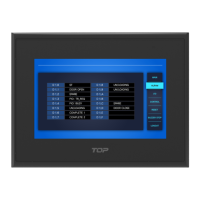
5.1.4 COM2 Connector pin number and Signal name
Type Pin No. Signal Direction Meaning
9Pin Female
1 RDA(RD+) Input RS-422/485 Receive Data (+)
2 RD(RxD)
Input RS-232C Receive Data
3 SD(TxD)
Output RS-232C Send Data
4 RDB(RD-)
Input RS-422/485 Receive Data (-)
5 SG
- Signal Ground
6 SDA(SD+) Output
RS-422/485 Send Data (+)
7 -
- Not Available
8 -
- Not Available
9 SDB(SD-) Output
RS-422/485 Send Data (-)
Be sure to connect the RD and SD to the RS-232C communication line by crossing each other with a
Twisted Pair Cable. Please connect SG directly.
RS-422/485 communication line must use RDA and RDB as Twisted Pair Cable, SDA and SDB
as Twisted Pair Cable.
Do not use shield wire of communication line as signal ground. It may cause communication failure.
5.2 Ethernet Communication Specifications
5.2.1 Ethernet
Item Specification
Ethernet Method IEEE802.3i/IEEE802.3u, 10BaseT / 100BaseT
Speed 10M / 100Mbps
Communication Method Base Band
Switching Method AUTO MDIX
Maximum Segment Length 100m (Hub between product)
Communication Cable UTP (Unshielded Twisted Pair)
Modular Jack RJ45
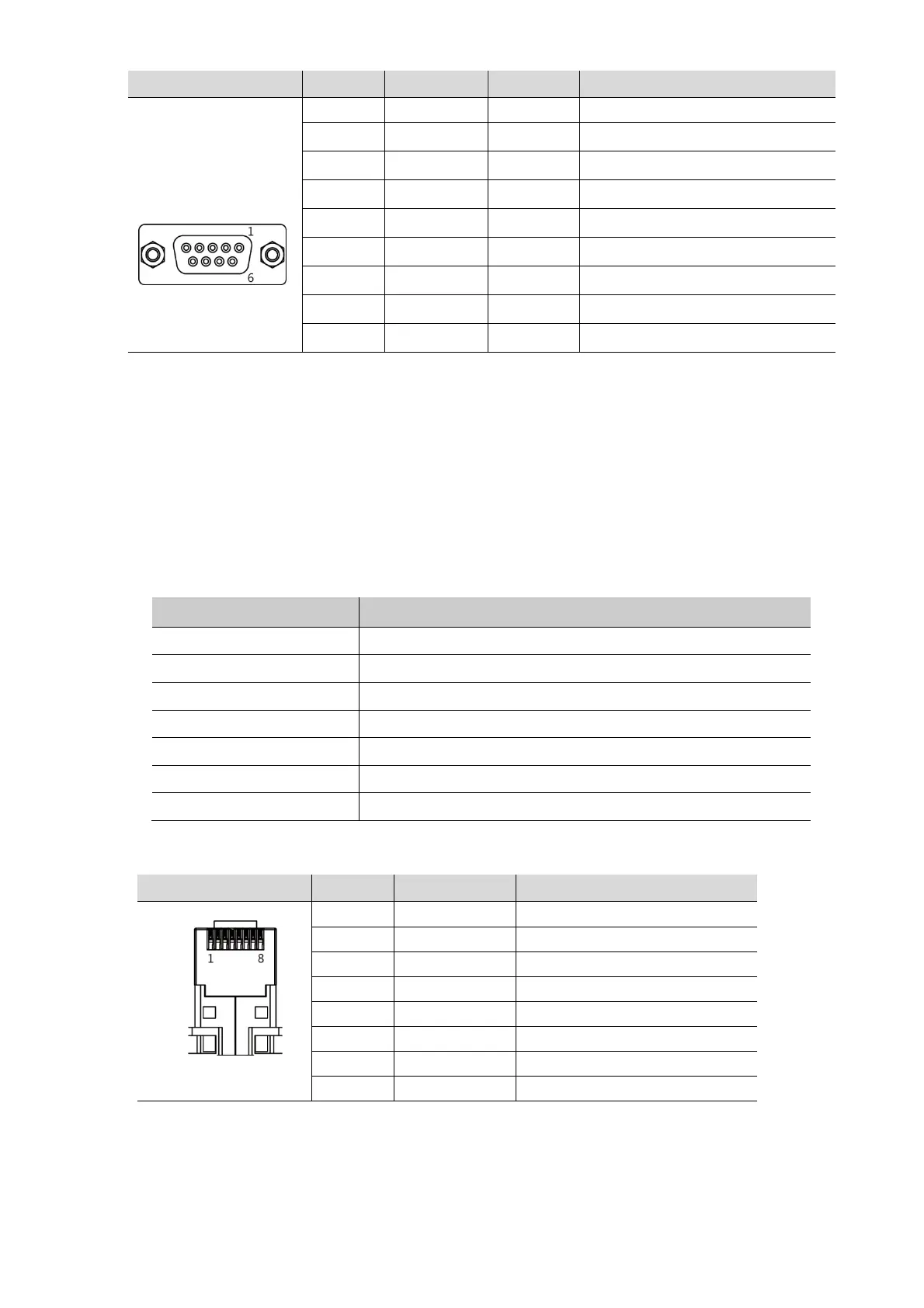
5.2.2 RJ–45 Pin Layout
Type Pin No. Color Signal
1 Orange/White TD+
2 Orange TD-
3 Green/White RD+
4 Blue Not Available in 10BaseT
5 Blue/White Not Available in 10BaseT
6 Green RD-
7 Brown/White Not Available in 10BaseT
8 Brown Not Available in 10BaseT
When HUB is using, Straight cable should be used.
Ex) Straight Cable Wiring: Connect 1:1 according to the wiring diagram above.
In case of do not using HUB,
Do not use HUB, when it is connected directly, Cross Cable should be used.
Ex) Cross Cable Wiring: In the above wiring diagram, TD+ and RD+ are changed,
and TD- and RD- are exchanged.