EasyManua.ls Logo

M2I XTOP07TW - COM1 RS-232 C Connector Pins and Signals; COM2 15-Pin RS-232 C Connector Pins and Signals; COM2 9-Pin RS-232 C Connector Pins and Signals

Default Icon
15 pages
Print Icon
To Next Page IconTo Next Page
To Previous Page IconTo Previous Page
Loading...
4
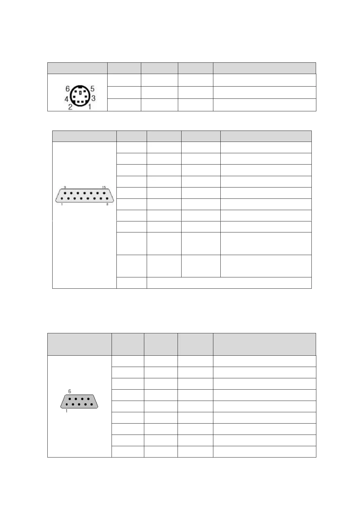
The Connector Pins and Signals of COM1(6Pin) with RS-232C Interface
The contents of Below Table are corresponding to all XTOP tyoe.
TYPE
Pin No.
Signal
Direction
Contents
6Pin Female
2
RD (RxD)
Input
Project file Receive (COM1)
6
SD (TxD)
Output
Project file Send (COM1)
3
SG
Signal Ground
The Connector Pins and Signals of COM2(15Pin) with RS-232C Interface
The contents of Below Table are corresponding to XTOP05MQ/05TQ/08TV/08TS S type, E type, and XTOP07 U type.
TYPE
Pin No.
Signal
Direction
Contents
15Pin Female
(COM2)
1
N/A
Not Used
2
RD(RxD)
Input
Data Receive
3
SD(TxD)
Output
Data Send
4
DTR
Output
Data Terminal Ready
5
SG
Signal Ground
6
DSR
Input
Data Set Ready
7
RTS
Output
Send Request Signal
8
CTS
Input
Send Enable Signal
9
RD(RxD)
Input
Project file Receive
(Acting as a COM1)
10
SD(TxD)
Output
Project file Send
(Acting as a COM1)
11~15
RS422/485 Serial Interface
Note: In case of 2 way communication by using COM1 port, you can download project file such as COM1 Port using
above No.9,10 pins.
The Connector Pins and Signals of COM2(9PIN) with RS-232C Interface
The contents of Below Table are corresponding to XTOP Standard Models like XTOP10TV/10TS/12TS/15TX&Economy
Model XTOP10TV-ED/ED-E&XTOP04TW
Type
Pin
No.
Signal
Direction
Contents
9Pin Female
1
N/A
Not Used
2
RD(RxD)
Input
Data Receive
3
SD(TxD)
Output
Data Send
4
DTR
Output
Data Terminal Ready
5
SG
Signal Ground
6
DSR
Input
Data Set Ready
7
RTS
Output
Send Request Signal
8
CTS
Input
Send Enable Signal
9
N/A
Not Used

Related product manuals