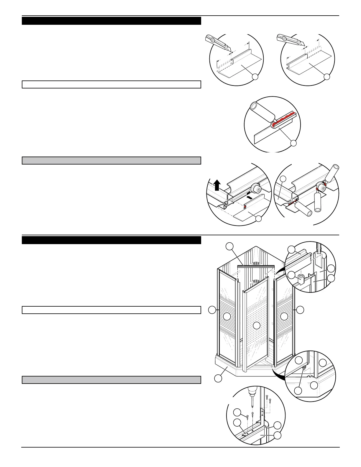
f) Depending on which way the door opens, remove, from one end or the other,
5/8” (16 mm) to the rigid (BLACK) part of the splash guard ribbon (K). Fig. 7.5.
g) Apply a bead of silicone in the groove of the splash guard ribbon (K). Fig. 7.6.
h) Insert the splash guard ribbon (K) under the door (J) by applying pressure
with a finger. Fig. 7.7.
(N). Fig. 7.7.
i) Apply silicone as shown in Fig. 7.8.
f) Selon le sens d’ouverture de la porte, retirez, à l’une ou l’autre des
extrémités du ruban, 5/8” (16 mm) de la partie rigide (noire) du ruban anti-
éclaboussure (K). Fig. 7.5.
g) Appliquez un cordon de silicone dans la rainure du ruban anti-éclaboussure
(K). Fig. 7.6.
h) Insérez le ruban anti-éclaboussure (K) sous la porte (J) en exerçant une
pression avec le doigt. Fig. 7.7.
(N). Fig. 7.7.
i) Appliquez de la silicone tel qu’illustré à la Fig. 7.8.
f) Según el lado de abertura de la puerta, quite del protector contra
salpicaduras -en uno u otro de sus extremos- un largo de 3/8” (16 mm)
únicamente de la parte rígida (NEGRA) Fig. 7.5.
g) Aplique un cordón de silicona en la ranura del protector contra salpicaduras
(K). Fig. 7.6.
h) Introduzca la banda protectora (K) por debajo de la puerta (J) presionando con
un dedo. Fig. 7.7.
(N). Fig. 7.7.
i) Aplique silicona tal como se muestra en la Fig. 7.8.
a) Position door by inserting pivot (O) at the bottom of door (J) into the
horseshoe shaped cavity on top of the shower base (1). Fig. 8.2.
b) Assemble top of door by sliding pivot (O) into the hole in the rail (L) and by
sliding the notches of the rail (L) into the top of the fixed panels (G and H).
Fig. 8.1. It would be preferable if a second person would be there to
render assistance in installing the rail.
c) Insert brackets (M) into the corners at the top of door. Fig. 8.3.
d) Fasten brackets with tapping screws #6-20 x 1/2” (13mm) (E) using an
electric drill. Fig. 8.3.
a) Positionnez la porte (J) en insérant le pivot (O) au bas de la porte dans la
cavité en forme de fer à cheval sur le dessus de la base (1). Fig. 8.2.
b) Assemblez le haut de la porte en insérant le pivot (O) dans le trou sous
le rail (L) et en faisant glisser les encoches du rail (L) dans le haut des
panneaux fixes (G et H). Fig. 8.1. Il est préférable de demander
l’aide d’une seconde personne pour procéder à l’installation du rail.
c) Insérez les renforts (M) dans les coins supérieurs de la porte. Fig. 8.3.
d) Fixez l’assemblage en position à l’aide des vis taraudeuses #6-20 x 1/2”
(13mm) (E) à l’aide d’une perceuse électrique. Fig. 8.3.
a) Coloque la puerta (J) introduciendo el pivote (O) de abajo de la puerta (J) en
la cavidad modelada en herradura arriba de la base de ducha (1). Fig. 8.2.
b) Monte la parte superior de la puerta introduciendo el pivote (O) en el
agujero debajo del riel (L) y deslizando las muescas del riel (L) en lo
alto de los paneles fijos (G y H). Fig. 8.1. Es preferible pedir a una
segunda persona que lo ayude para efectuar la instalación del riel.
c) Inserte los soportes escuadra (M) en las esquinas superiores de la puerta. Fig. 8.3.
d) Fije los soportes de todo el montaje con los tornillos autotrabadores #6-20
x 1/2” (13 mm) (E) con un taladro eléctrico. Fig. 8.3.
8 10009908
Inside
Intérieur
Interior
K
Q
K
K K
Right opening
Ouverture à droite
Abertura a la derecha
Right opening
Ouverture à droite
Abertura a la derecha
Left opening
Ouverture à gauche
Abertura a la izquierda
A
G H
A
1
J
L
H
O
1
H
J
J
O
L
E
H
L
M


 To Next Page
 Loading...