Do you have a question about the Mackie Onyx 80 series and is the answer not in the manual?
Advises on reducing electric shock risk, avoiding cover removal, and seeking qualified service personnel for repairs.
Details risks of hearing loss from high noise levels and provides OSHA exposure limits and recommendations for hearing protection.
Warns users to avoid exposing the apparatus to rain or moisture to prevent fire or electric shock hazards.
Details the procedure for adjusting input GAIN controls to achieve optimal signal levels for each channel.
Describes the GAIN control for adjusting input sensitivity for mic and line inputs.
Provides a hardware bypass for the Perkins EQ circuitry, allowing A/B comparison of EQ'd vs. un-EQ'd signals.
Explains the purpose of AUX Sends for effects processing or stage monitoring and their control.
Controls the output level of the channel, from off to unity gain and beyond.
Adjusts input sensitivity for stereo Aux Inputs to optimal operating levels.
Explains how Aux Sends 1-6 on Aux Inputs 1-8 are routed to specific Aux Send buses.
Controls the output level of the stereo Aux Input channels.
Controls the overall level of each of the eight Auxiliary Sends before they are delivered to the outputs.
Controls the Group's signal level, from off to unity gain and beyond.
Master faders controlling the output levels at the MAIN OUTS.
Controls the signal level at the Left and Right MONITOR OUTS.
Controls the signal level at the stereo headphone output.
Female XLR connector for balanced microphone input, featuring Onyx mic preamps.
1/4" TRS connector for balanced or unbalanced line-level input signals.
1/4" TRS jacks for connecting serial effects devices, acting as send/return points.
DB-25 connectors providing balanced direct outputs for eight channels each, post-GAIN and pre-EQ.
1/4" TRS connectors for balanced or unbalanced line-level stereo signals from external processors.
1/4" TRS outputs providing balanced or unbalanced signals for effects devices or stage monitors.
1/4" TRS outputs providing balanced or unbalanced signals for connecting to line-level devices.
Female XLR input for connecting an external talkback microphone (dynamic recommended).
Male XLR output providing a balanced line-level combination of Left and Right Main Mix signals.
XLR and 1/4" TRS outputs for balanced line-level signals representing the final mixed stereo output.
1/4" TRS jacks providing a balanced line-level signal for monitoring or additional main mix outputs.
Standard 3-prong IEC connector for detachable linecord, supporting universal AC voltage.
Powers the unit on or off, supplying power to the mixer and front panel LEDs.
Details warranty terms and the process for obtaining service or repairs within the warranty period.
Checks to perform if the mixer is not receiving power, including cord, outlet, and switch verification.
Steps to diagnose output issues, checking levels, connections, and isolating mixer vs. external device problems.
Guides for diagnosing problems with individual channels, checking mute, gain, fader, and signal source.
Addresses problems related to distortion, noise, or hum, guiding users to check inputs, levels, and cabling.
Provides steps to identify and eliminate noise or hum by checking inputs, channels, and grounding.
Outlines the steps for sending the mixer for service, including contacting Tech Support and packaging requirements.
Provides the pinout diagram and wiring details for DB25 connectors used for direct channel outputs.
Details the EQ bands, frequencies, and boost/cut ranges for mono and stereo channels.
Lists power consumption figures for each Onyx 80 Series model and universal AC supply voltage.
Visual representation of the mixer's internal signal flow and interconnections between different sections.
Details the three-year limited warranty, repair/replacement policy, and coverage limitations.
Explains the process for obtaining warranty repairs, including contacting support and providing documentation.
Provides step-by-step instructions for obtaining factory-authorized service, including obtaining a Service Request Number.
LOUD Technologies' right to inspect products and require proof of purchase for warranty claims.
Details the timeframe for repairs/replacements and the use of refurbished parts.
| Brand | Mackie |
|---|---|
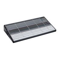
| Model | Onyx 80 series |
| Category | Music Mixer |
| Language | English |