10
SRM | V-CLASS HIGH-PERFORMANCE POWERED LOUDSPEAKER SERIES
SRM | V-CLASS HIGH-PERFORMANCE POWERED LOUDSPEAKER SERIES
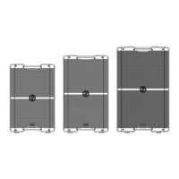
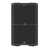
SRM210 V-CLASS
Frequency Range (–10 dB)
Rango de frecuencias (–10 dB)
Plage de fréquence (–10 dB)
Frequenzbereich (–10 dB)
45 Hz – 20 kHz
Coverage Pattern
Patrón de cobertura
Couverture sonore
Abstrahlverhalten
90˚ horizontal x 60˚ vertical (vertikal)
Maximum SPL Peak
SPL máximo en picos
Niveau de pression sonore max (peak)
Maximaler Schalldruck
3 dB
Total System Power
Potencia total del sistema
Puissance totale du système
Gesamtleistung des Systems
2000 watts peak
2000 watios en picos
2000 watts crête
2000 Watt Spitze
Low Frequency
Graves
Basses fréquences
Bässe
0 in / 254 mm woofer, 800 watts peak, Class D power amplifier
Woofer de 0 in / 254 mm, Etapa de potencia clase D y 800 watios en picos
Woofer de 0" / 254 mm, Ampli de puissance Classe D 800 watts crête
0“ / 254 mm Woofer, 800 Watt Spitze Class D Endstufe
High Frequency
Agudos
Hautes fréquences
Höhen
.4" / 36 mm polymer compression driver – 200 watts peak Class D power amplifier
Cabezal de compresión fabricado en polímero de .4" / 36 mm –Etapa de potencia de clase D y 200 watios en picos
Moteur de compression en polymère d‘,4" / 36 mm –Ampli de puissance Classe D 200 watts crête
,4“ / 36 mm Polymer-Kompressionstreiber – 200 Watt Spitze Class D Endstufe
Crossover Point
Frecuencia de corte del crossover
Fréquence de coupure
Trennfrequenz
2.0 kHz
Input Type
Tipo de entrada
Type d’entrée
Eingangstyp
2 x Female XLR – /4" balanced TRS combo jack and /8» Stereo
2 x clavijas combo XLR – TRS de 6,3 mm balanceadas hembra y 3,5 estéreo
2 connecteurs combinés XLR – Jack symétrique 6,35 mm et 3,5 stéréo
2 symmetrische XLR / 6,3 mm TRS-Kombibuchsen und 3,5 mm Stereo
Output
Salida
Sortie
Ausgang
Male XLR balanced [Direct Out, Mix Out]
XLR macho balanceado [Direct Out, Mix Out]
XLR mâle symétrique [Direct Out, Mix Out]
XLR-Stecker symmetrisch [Direct Out, Mix Out]
Power Requirements
Alimentación
Alimentation
Spannungsbedarf
~00 – 240 VAC, 50-60 Hz, 0W
or / ou / oder
~220V – 240V, 50 – 60 Hz, 0 W
Protection Features
Funciones de protección
Protections
Schutzfunktionen
Peak and RMS limiting, power supply and amplifier thermal protection,
overcurrent, over-voltage, dynamic thermal protections and forced air-cooling
Limitación de picos y RMS, protección contra recalentamiento de fuente de alimentación y amplificador,
sistemas de protección contra sobretensiones, sobre-voltajes y térmico, así como sistema de refrigeración forzada
Limitation crête et ecace, protection contre la surchaue de l’alimentation et de l’amplificateur,
surintensité, surtension, protection thermique dynamique et refroidissement par air forcé
Peak- und RMS-Limiting, Überhitzungsschutz für Netzteil und Verstärker,
Überstrom, Überspannung, dynamischer Überhitzungsschutz und Umlufkühlung
Size (H x W x D)
Tamaño (A x L x P)
Dimensions (H x L x P)
Abmessungen (H x B x T)
23.0 x 5. x 2.9 in
584 x 384 x 328 mm
Weight | Peso | Poids | Gewicht 30.9 lb / 4.0 kg
Technical Specifications / Especificaciones técnicas
Caractéristiques techniques / Technische Daten
SRM212 V-CLASS SRM215 V-CLASS
42 Hz – 20 kHz 40 Hz – 20 kHz
90˚ horizontal x 60˚ vertical (vertikal)
35 dB 36 dB
2000 watts peak
2000 watios en picos
2000 watts crête
2000 Watt Spitze
2 in / 305 mm woofer, 800 watts peak, Class D power amplifier
Woofer de 2 in / 305 mm, Etapa de potencia clase D y 800 watios en picos
Woofer de 2" / 305 mm, Ampli de puissance Classe D 800 watts crête
2“ / 305 mm Woofer, 800 Watt Spitze Class D Endstufe
5 in / 38 mm woofer, 800 watts peak Class D power amplifier
Woofer de 5 in / 38 mm, Etapa de potencia clase D y 800 watios en picos
Woofer de 5" / 38 mm, Ampli de puissance Classe D 800 watts crête
5“ / 38 mm Woofer, 800 Watt Spitze Class D Endstufe
.4" / 36 mm polymer compression driver – 200 watts peak Class D power amplifier
Cabezal de compresión fabricado en polímero de .4" / 36 mm –Etapa de potencia de clase D y 200 watios en picos
Moteur de compression en polymère d‘,4" / 36 mm –Ampli de puissance Classe D 200 watts crête
,4“ / 36 mm Polymer-Kompressionstreiber – 200 Watt Spitze Class D Endstufe
2.0 kHz
2 x Female XLR – /4" balanced TRS combo jack and /8» Stereo
2 x clavijas combo XLR – TRS de 6,3 mm balanceadas hembra y 3,5 estéreo
2 connecteurs combinés XLR – Jack symétrique 6,35 mm et 3,5 stéréo
2 symmetrische XLR / 6,3 mm TRS-Kombibuchsen und 3,5 mm Stereo
Male XLR balanced [Direct Out, Mix Out]
XLR macho balanceado [Direct Out, Mix Out]
XLR mâle symétrique [Direct Out, Mix Out]
XLR-Stecker symmetrisch [Direct Out, Mix Out]
~00 – 240 VAC, 50-60 Hz, 0W
or / ou / oder
~220V – 240V, 50 – 60 Hz, 0 W
Peak and RMS limiting, power supply and amplifier thermal protection,
overcurrent, over-voltage, dynamic thermal protections and forced air-cooling
Limitación de picos y RMS, protección contra recalentamiento de fuente de alimentación y amplificador,
sistemas de protección contra sobretensiones, sobre-voltajes y térmico, así como sistema de refrigeración forzada
Limitation crête et ecace, protection contre la surchaue de l’alimentation et de l’amplificateur,
surintensité, surtension, protection thermique dynamique et refroidissement par air forcé
Peak- und RMS-Limiting, Überhitzungsschutz für Netzteil und Verstärker,
Überstrom, Überspannung, dynamischer Überhitzungsschutz und Umlufkühlung
25.9 x 5.2 x 4.2 in
658 x 386 x 36 mm
28.8 x 7.6 x 5.4 in
732 x 447 x 39 mm
40.6 lb / 8.4 kg 48.9 lb / 22.2 kg
 Loading...