Do you have a question about the Mackie THUMP 212 and is the answer not in the manual?
Describes the standard IEC power connector and the correct procedure for plugging into an AC outlet.
Explains the operation of the power switch and the recommended sequence for powering equipment on and off.
Details the balanced and unbalanced wiring for XLR and 1/4" inputs, including AES standards.
Describes the 1/8" line-level input for connecting devices like phones, tablets, and MP3 players.
Explains how the Mic/Line switch optimizes input sensitivity for microphone or instrument signals on Channel 1.
Guides on setting input gain levels for optimal sound quality and performance for both channels.
Details the male XLR Thru jack used for daisy-chaining the signal from input jacks to other loudspeakers.
Explains how the main volume knob controls the overall signal level delivered to the internal power amplifiers.
Describes the dual-colored LED indicating signal presence (green) and limiter activation (red).
Explains the Music Ducking feature that automatically lowers Ch. 2 volume when Ch. 1 receives a mic signal.
Details the multi-band feedback eliminator designed to automatically reduce unwanted audio frequencies.
Explains the fan switch for cooling the speaker, with an indicator LED showing when the fan is active.
Allows selection of fan speed from 1 (lowest) to 5 (highest) via button presses, indicated by LED flashes.
Describes a feature for misting, possibly a humorous or specific function not detailed.
Explains the heater switch for warming the speaker, with an indicator LED showing when the heat is active.
Allows selection of heat level from 1 (low) to 5 (high) via button presses, indicated by LED flashes.
Controls rotation speed (1-3) for fan/heater, requires specific mounting solutions for operation.
Explains the high frequency driver's compression circuit protecting against damaging transient peaks.
Details the subsonic filter preventing woofer damage from ultra-low frequencies that cause bottoming out.
Describes the automatic thermal shutdown and reset mechanism that activates if the amplifier overheats.
Provides common solutions for issues like no power, no sound, poor sound quality, and general operational problems.
Offers solutions for noise issues, including cable routing, power circuit considerations, and EMI reduction.
Provides troubleshooting steps for hum issues, focusing on ground loops and the use of balanced connections.
Directs users to contact Technical Support for any problems not covered in the troubleshooting sections.
Guides users on obtaining warranty and non-warranty service, including locating authorized service centers.
Details frequency response, coverage angles, maximum SPL, and monitor angle for the loudspeaker models.
Lists specifications for the low and high-frequency drivers, including size and type.
Provides details on rated power, THD, cooling methods, and design for the internal power amplifiers.
Specifies input types, impedance for mic/line, 1/8" line, and Thru Out connections on the rear panel.
States the crossover frequency used in the electronic crossover system of the loudspeakers.
Details power requirements, including the detachable line cord and AC connector type for the unit.
Lists safety features such as input protection, feedback eliminator functionality, and display LED indicators.
Provides dimensions and weight specifications for both the Thump212 and Thump215 loudspeaker models.
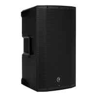
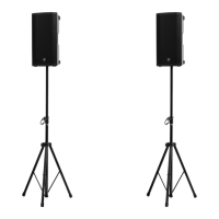
Explains floor and pole mounting options, emphasizing stability and cautioning against rigging.
Lists available accessories such as speaker bags and tripod stands, including their respective part numbers.
| Type | Powered Loudspeaker |
|---|---|
| Power | 1400W |
| Frequency Response | 47Hz - 23kHz |
| Max SPL | 128 dB |
| Enclosure Material | Polypropylene |
| Woofer Size | 12 inches |
| Tweeter Size | 1 inch |
| Outputs | XLR |
| Depth | 14 in (356 mm) |
| Height | 24.2 inches / 615 mm |
| Width | 14.1 inches / 359 mm |