2015_03_03 2
3.1 Definition of pictograms on type identification label
Installation in return flow
Installation in forward flow
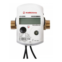
4 Mounting the Flow Sensor
- Flush the pipes according the generally acknowledged rules of technology. Then close all the shut-off
valves. Open the nearest draining valve for pressure release.
- Drain the closed-off pipe section.
- Loosen the coupling rings and remove the old heat meter.
- Remove all old gaskets.
- Clean the sealing surfaces.
- Insert new gaskets.
- Position the flow sensor correctly, taking into account the direction of flow (arrow on the side of the flow
sensor)!
- Tighten the coupling rings.
- Detach the calculator and mount it, or rotate it to the best position for read-out.
Note
In order to simplify mounting in narrow installation spaces the calculator can be detached from the flow sensor.
To release the calculator pull it carefully up off the flow sensor.
For heat meter versions it is recommended to detach the calculator.
For heat/cooling meters the calculator must be detached from the flow sensor.
5 Mounting the Temperature Sensors
For pipes of sizes < DN25 in new installations (whether new construction or refurbishment) it is required to install
the temperature sensors directly immersed in the flow (without temperature pockets).
Note
During installation of the meter make sure that the temperature sensors are mounted according to their marking.
5.1 Direct mounting (ball valve and T-piece)
- Remove the blind plug/old temperature sensor and gasket/old O-ring. Clean connection surfaces.
- Slide the O-ring off the temperature sensor and insert it to the bottom of the threaded opening of the ball
valve or the T-piece.
- Insert the temperature sensor to at least 15 mm, preferably the middle of the ball valve or T-piece (or a
little further) and screw tightly. It is important to pay attention that the tip of the temperature sensor does
not touch the bottom (the other side) of the ball valve or T-piece.