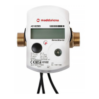
Energy Meter
microCLIMA
Installation and Operating Instructions
V. 1.03 October’06
microCLIMA
Contents
1 GENERAL INFORMATION
2 MOUNTING THE FLOW SENSOR
3 MOUNTING THE TEMPERATURE SENSORS
3.1 Installation in a temperature pocket
3.2 Installation in a ball valve
4 START OF OPERATION
5 TECHNICAL DATA
6 THE DISPLAY SETUP
7 DISPLAY INFORMATION
8 ERROR CODES
9 INTERFACES / OPTIONS
9.1 Infrared
9.2 M-bus
9.3 Contacts
10 MOUNTING WITH WALL SUPPORT
1. General Information
•
The valid standard for the application of heat
meters is EN 1434, parts 1 + 6. The regulations
for electrical installations are to be observed.
•
The heat meter left the factory in conformance
with all applicable safety regulations. All main-
tenance and repair work is to be carried out
only by qualified and authorized technical per-
sonnel.
• All details and specifications listed on the data
sheet of the heat meter must be adhered to.
•
The seals and locking wires required for the
verification of the heat meter mustn’t be dam-
aged or removed – otherwise the verification
and guarantee of the instrument no longer ap-
ply!
• All electrical connections must be laid at a
minimum distance of 20 cm to sources of
electromagnetic interference (switches, control-
lers, pumps, etc.) In addition, all instrument
connections must be laid at a
minimum dis-
tance of 5 cm to other current-carrying wires.
•
The temperature sensor cables must not be
kinked, rolled up, lengthened or shortened.
• To protect against damage and dirt the heat
meter should only be removed from the packag-
ing directly before installation.
• To clean the heat meter (only if necessary) use
a slightly moist (not dripping wet!) cloth.
• According to the weights and measures regula-
tions on verification, the verification period in
Germany for heat meters is 5 years.
•
If several heat meters are installed in one unit,
care must be taken to ensure that all the meters
have the same installation conditions.
•
Pay attention to the mounting location of the
heat meter: return flow pipe unless the optional
forward flow version was ordered.
•
In the case of heat meters with two declarations
on the identification plate, such as:
Q≥ 24l/h ∆T: 3-100 K / Q≥ 12l/h ∆T: 6-100K
the declaration that is not valid for the local in-
stallation situation must be made unrecogniz-
able. For example, for floor heating:
Q≥ 24l/h ∆T: 3-100 K / Q≥ 12l/h ∆T: 6-100K
for example, for radiator heating:
Q≥ 24l/h ∆T: 3-100 K / Q≥ 12l/h ∆T: 6-100K
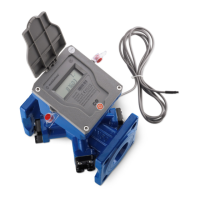
2. Mounting the Flow Sensor
-
Close shut-off valves
-
Unscrew the union nut (coupling ring)
- Remove old gaskets
-
Clean the sealing surfaces
-
Insert new gasket
-
Lubricate the external thread of the flow sensor
with a thin layer of silicone grease
-
Position the flow sensor correctly, taking into
account the direction of flow
-
Tighten the union nut (coupling ring)
- Rotate the calculator into the correct reading
position
Note:
In order to simplify mounting in a narrow installa-
tion space the calculator can be removed from the
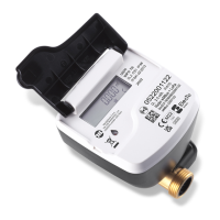
flow sensor. To separate the calculator press on
the side surfaces shown in the illustration and
carefully lift off the top part of the housing.