Energy Meter
microCLIMA
Installation and Operating Instructions
V. 1.03 October’06
microCLIMA
3. Mounting the Temperature Sensors
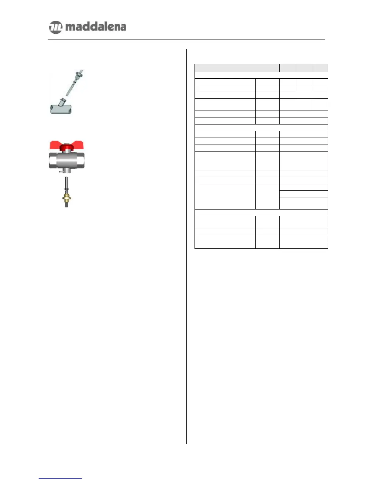
3.1. Installation in temperature pocket
-
Place the O-ring in the middle
groove. Slide the sealing
screw nut up to the O-ring.
-
Holding the screw nut in
place, insert the sensor into
the ball valve and tighten the
screw nut.
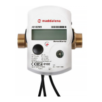
3.2. Installation in a ball valve
-
Remove the blind cap or plug
and its gasket. Check that all
surfaces are clean.
-
Place the O-ring in the groove
closest to the tip of the
sensor. Slide the sealing
screw nut up to the O-ring.
-
Holding the screw nut in
place, insert the sensor into
the ball valve and tighten the
screw nut.
4. Start of Operation
-
Slowly open the shut-off valves
- Check for leakage and proper functioning
-
Clean the calculator
After confirming that the heat meter is functioning
properly, insert and tighten the sealing wires for
the temperature sensors and the heat meter itself.
When replacing a meter at the end of a verification
period note the meter readings and the serial
numbers of the old and new meters.
Please also check the following points:
• Is the heat meter the appropriate size?
• Is the heating system in operation?
• Are the shut-off valves open?
• Is the heating system clear (dirt filters not
clogged)?
• Are the temperature sensors sealed with
wires (to avoid tampering)?
• Is the directional arrow on the flow sensor
in the correct direction?
• Is a flow volume displayed?
• Is a plausible temperature difference dis-
played?
• For instruments with two external temp-
erature sensors, is the forward flow sensor
(red) in the forward flow and the return flow
sensor (blue) in return flow pipe?
• For instruments with a built-in return flow
temperature sensor, is the flow sensor
mounted in the return flow?
5. Technical Data
Type 0.6 1.5 2.5
Flow sensor
Nominal flow m
3
/h 0.6 1.5 2.5
Maximum flow m
3
/h 1.2 3.0 5.0
Nominal pressure bar 10
Low flow horizontal
threshold vertical
l/h
3.5
4
7
7
10
10
Temperature range °C 15…90
Mounting position
any
Calculator
Ambient temperature °C 5…55
Temperature range °C 1…130
Temperature difference K 3…100
Power supply 3 V, Lithium
Operating life Years
(10 + 1 optional)
Data storage E²PROM, daily
Display 8-digit
Infrared
M-bus (optional)
Interfaces
Pulse output
(optional)
Temperature sensors
Type
Platinum precision
resistor
Connection 2-wire technique
Diameter mm 5.0 (optional 5.2)
Cable length m 1.5 (optional 3.0)
6. The Display Set-up
The calculator has a liquid crystal display with 8
digits and special characters. The values that can
be shown are divided into three display loops.
• main loop
• technician’s loop
• statistics loop
All data is retrieved using the key next to the dis-
play. The standard display has been set to perma-
nently show the total heat quantity consumed since
the meter was put into operation.
At the start you are automatically in the main loop.
By pressing the key longer than 4 seconds you
change to the next loop. Keep the key pressed
until you reach the desired information loop.
To change the information display within a loop,
simply give a short press to the key. In this way,
you can scan all the information in the loop.
After one minute of non-use, the display returns to
the total heat quantity, the standard display.