OPERATION
VEHICLE ELECTRICAL SYSTEM
Operating Manual MT 25 / 30 YT 81
Vehicle fuses
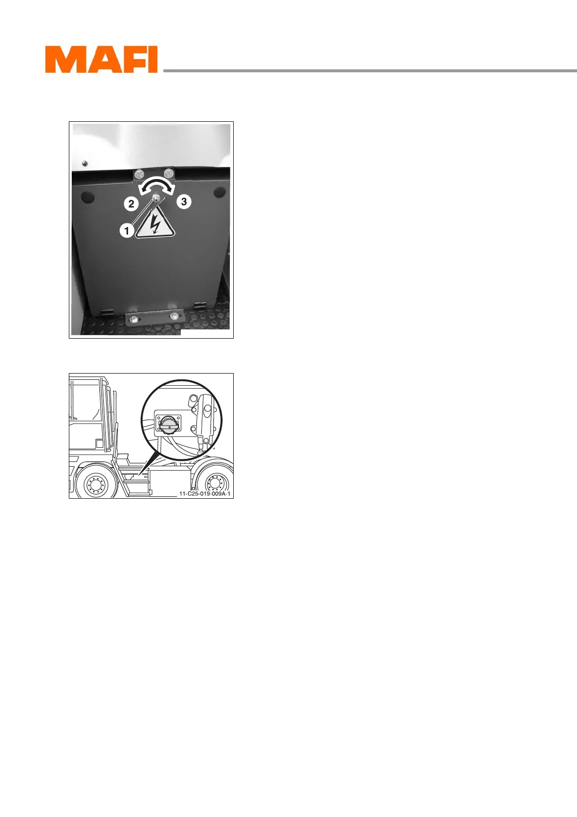
Fig. 74: Central electric box
1 Screw-on cap
2 lock
3 unlock
The electrical vehicle fuses are located to the right of the
operator in a compartment.
The exact layout can be read from the supplied circuit
diagram.
External start socket – optional
Fig. 75: External start socket
The external start socket is located on the left side of the vehi-
cle between the entrance steps. The socket can be used to
give or receive starting aid.